lock or a seal to prevent unauthorized changes to the switch position as is sometimes required for audit compliance.
Important When a mechanical lockout device is required, the lockout must be installed in the switch at the
factory. A lockout mechanism cannot be added to an existing Scanner 3100 control switch after the
switch is installed.
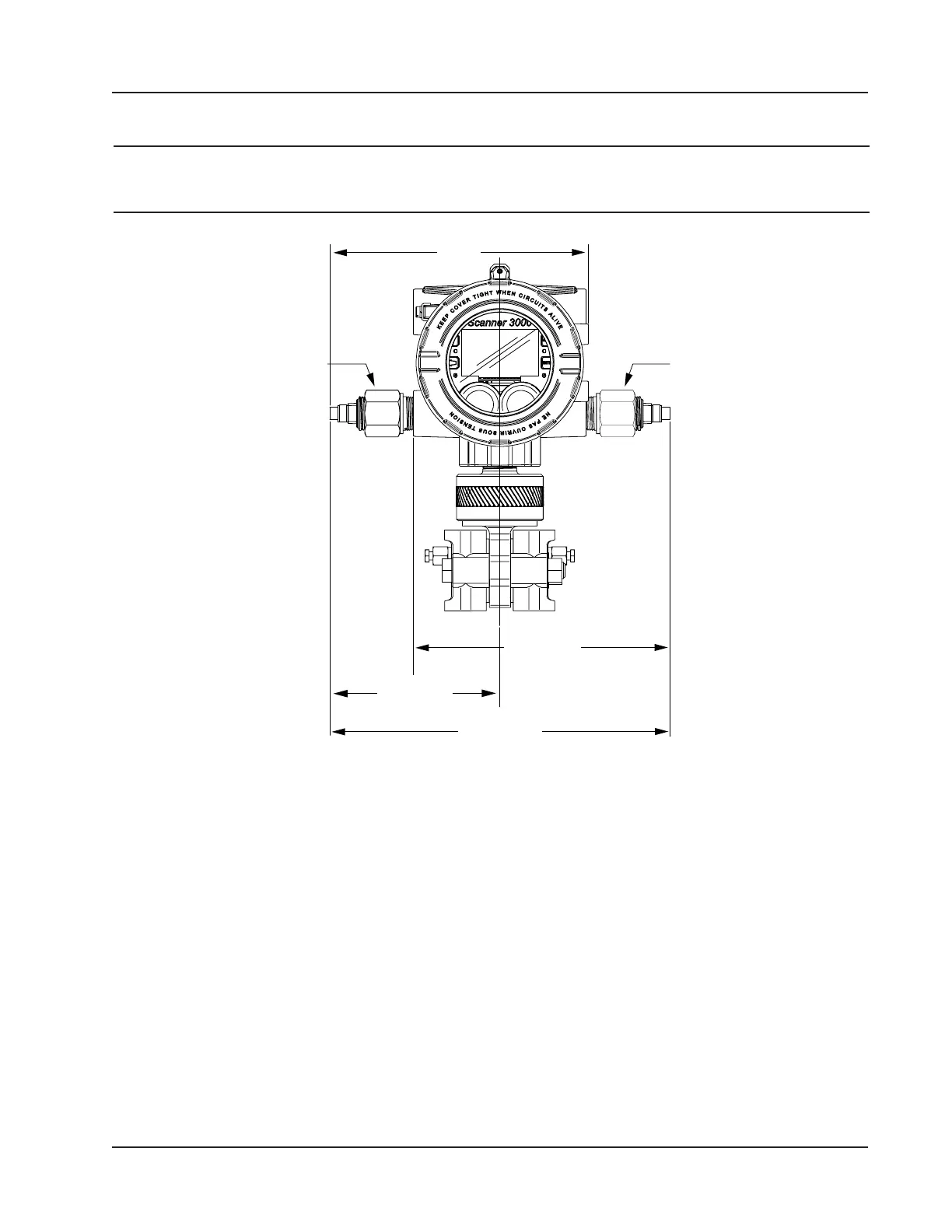
(204.7)
switch
Approx. 8.0
(204.7)
Approx. 5.3
(134.07)
Approx. 10.6
Figure 1.5—Control switch dimensions in inches (mm); the above diagram shows the default locations of factory-installed
switches
Explosion-Proof RTD Assembly
The Barton Model 21 RTD, shown in Figure 1.6, page 12, is a 4-wire, 100-ohm explosion-proof RTD assembly that
can be connected to the Scanner 3100 without conduit in a Class I, Division 1 installation. Factory-sealed, armored leads
are covered in PVC. The RTD assembly can be ordered with teck cable lengths of 5, 10, or 30 ft, and is available with a
6-in. or 12-in. RTD probe.
The Model 21 RTD is CSA certied for use in Class I, Groups B, C, and D; Class II, Groups E, F and G; and Class III
hazardous area environments.
Each RTD assembly is tted with 1/2-in. and 3/4-in. connectors for adapting to various size conduit openings and thread-
olets. The RTD is eld-adjustable for insertion lengths of up to 12 in. For wiring instructions, see Figure 3.6, page 59.
For part numbers, see Table 7.3—RTD and Cable Assemblies, page 89.
11
Scanner 3100 EFM Section 1