Remote-Mount Antenna for Pipe Outside Diameters of 2 3/8 Inches
Cameron’s optional pipe mount kit accommodates mounting the remote antenna to a 2-in. pipe with a 2 3/8-in. outside
diameter. The hardware kit includes a stainless steel L-shaped bracket, two U-bolts, four U-bolt nuts, two stainless steel
5/16-18 bolts (3.25-in. long), two 5/16-in. lock washers, two 5/16-in. at washers and two 5/16-in. nuts.
Important One of the toothed brackets shipped with the standard pole-mount kit is also required for this
installation. Do not discard the standard pole-mount kit antenna packaging before locating the
toothed brackets.
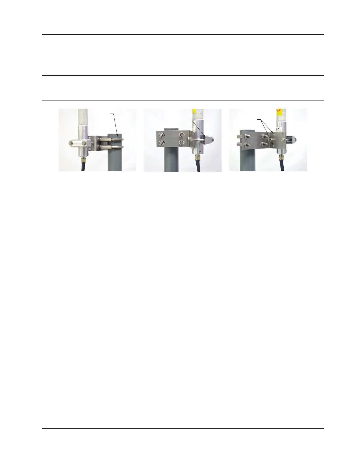
U-bolt (2) Toothed bracket
(ships with antenna)
Top and bottom holes
are not used
Figure 2.8—Optional 2-in. pipe mount bracket
To install the antenna, reference Figure 2.8 while following the instructions below:
1. Remove one of the toothed brackets from the standard pole-mount kit antenna packaging for use with the optional
hardware kit. The remaining hardware in the antenna package will not be used for this installation.
2. Position the L-shaped bracket against the pipe so that the pipe is on the outside of the “L” and secure it to the pipe
with the two U-bolts and four U-bolt nuts (Figure 2.8, left). The U-bolts will pass through the widest panel of the
“L” bracket.
3. Position the antenna against the bracket so that the shiny metal base is touching the bracket and the capped end of
the antenna is vertical in the air. Note the N-female cable connector at the bottom of the metal base for connecting
antenna cable.
4. Place the toothed bracket against the adjacent L-bracket panel (shortest of the two panels) so that the toothed, round-
ed edge faces the L-bracket panel and the holes in the toothed bracket align with the center holes in the L-bracket.
5. Place a at washer over each of the 5/16-in. bolts and insert the bolts through the holes in the toothed bracket and
through the center holes in the L-bracket panel (Figure 2.8, center and right).
6. Attach a lock washer and a nut to each of the bolts on the inside of the L-shaped bracket to hold the toothed bracket
loosely in place.
7. Position the antenna between the toothed bracket and the L-shaped bracket so that the rounded edge of the toothed
bracket ts snugly against the curvature of the shiny antenna base and the brackets clamp around the approximate
center of the antenna base.
8. Holding the antenna in place, tighten the two 5/16-in. nuts on the inside of the L-bracket to secure the antenna (Fig-
ure 2.8, right).
9. Attach the antenna cable to the N-female cable connector at the bottom of the antenna.
Industry Standard Compliance
To ensure measurement accuracy, ow runs and turbine meter runs must be installed in accordance with the industry
standards listed in Table 2.2—Industry Standards for Meter Installation, page 36. For a complete list of industry stan-
dards used in the development of ow rate and uid property calculations, see Table 1.4—Flow Rate Standards, page
23 and Table 1.5—Fluid Property and Energy Flow Calculations, page 24.
35
Scanner 3100 EFM Section 2