Input Wiring
Turbine Flowmeter Inputs
TFM inputs 1, 2 and 3 on the terminal board provide the turbine owmeter input signal generated by a magnetic pickup,
enabling the Scanner 3100 to calculate and display instantaneous ow rates and accumulated totals. Wire as shown in
Figure 3.5.
BLACK
RED
A
B
Pickup Input
Figure 3.5—Flowmeter input
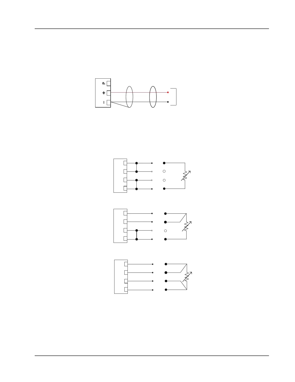
RTD Inputs
The 4-wire RTDs described in Appendix A of this manual are recommended for measuring temperature in temperature-
compensated gas and liquid calculations, though a 2- or 3-wire RTD may prove functional. Wiring is essentially the same
for all three models, though wire color may vary as indicated. Wire as shown in Figure 3.6.
WHITE
RED
RTD+
RTD-
I+
I-
JUMPER
JUMPER
3-Wire
WHITE
RED
WHITE
JUMPER
RTD+
RTD-
I+
I-
4-Wire
WHITE
WHITE
RED
RTD+
RTD-
I+
I-
I+
R+
R- I-
RTD 1, 2
I+
R+
R- I-
RTD 1, 2
I+
R+
R- I-
RTD 1, 2
Figure 3.6—Process temperature input
59
Scanner 3100 EFM Section 3