Section 3—Wiring the Scanner 3100 EFM
Field Wiring Connections
!
WARNING: Do not connect/disconnect equipment or change batteries unless the area is known to be non-
hazardous. The Scanner 3100 poses no hazard when opened in a safe area.
CAUTION All eld wiring must conform to the National Electrical Code, NFPA 70, Article 501-4(b) for installa-
tions within the United States or the Canadian Electric Code for installations within Canada. Local
wiring ordinances may also apply. All eld wiring must be rated for temperatures of 90 degC or
higher, and have a wire range of 22 to 14 AWG. Terminal block screws must be tightened to a mini-
mum torque of 5 to 7 in-lb. (0.57 to 0.79 joules) to secure the wiring within the terminal block. Only
personnel who are experienced with eld wiring should perform these procedures.
To wire the Scanner 3100 for operation, complete the following eld connections:
1. Remove the rear cover of the enclosure to access the terminal board. All wiring connections can be made to this
board with the exception of the lithium batteries. Wire in accordance with the wiring diagrams shown on page 58
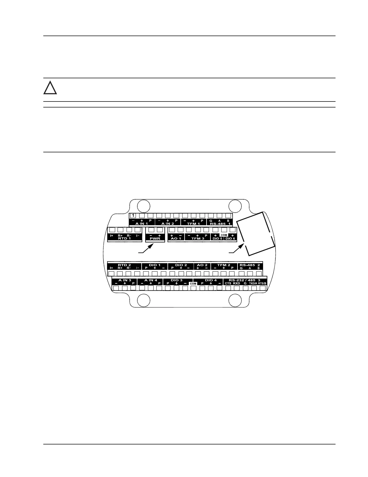
through page 65. See Figure 3.1 for help in locating the terminals by number.
Power Ethernet
2 3 4 5 6 7 8 9 10 11 12
13 14 15 16 17 18 19 20 21 22 23 24 25 26
27 28 29 30 31 32 33 34 35 36 37 38 39 40 41 42 43 44
45 46 47 48 49 50 51 52 53 54 55 56 57 58 59 60 61 62
Figure 3.1—Terminal board illustration with numbered terminals
2. Complete wiring of the terminal board as follows:
a. Connect wiring for external power to PWR (Terminals 17 and 18), if desired.
b. If the device is externally powered, route the protective earth grounding conductor into the enclosure with the
incoming power conductors and terminate it to the screw in the top of the enclosure (Figure 3.2, page 56).
Alternatively, connect an earth ground conductor to the external stainless steel ground lug of the enclosure and
to a ground rod or other suitable system earth ground, as shown in (Figure 3.2, page 56).
55
Scanner 3100 EFM Section 3