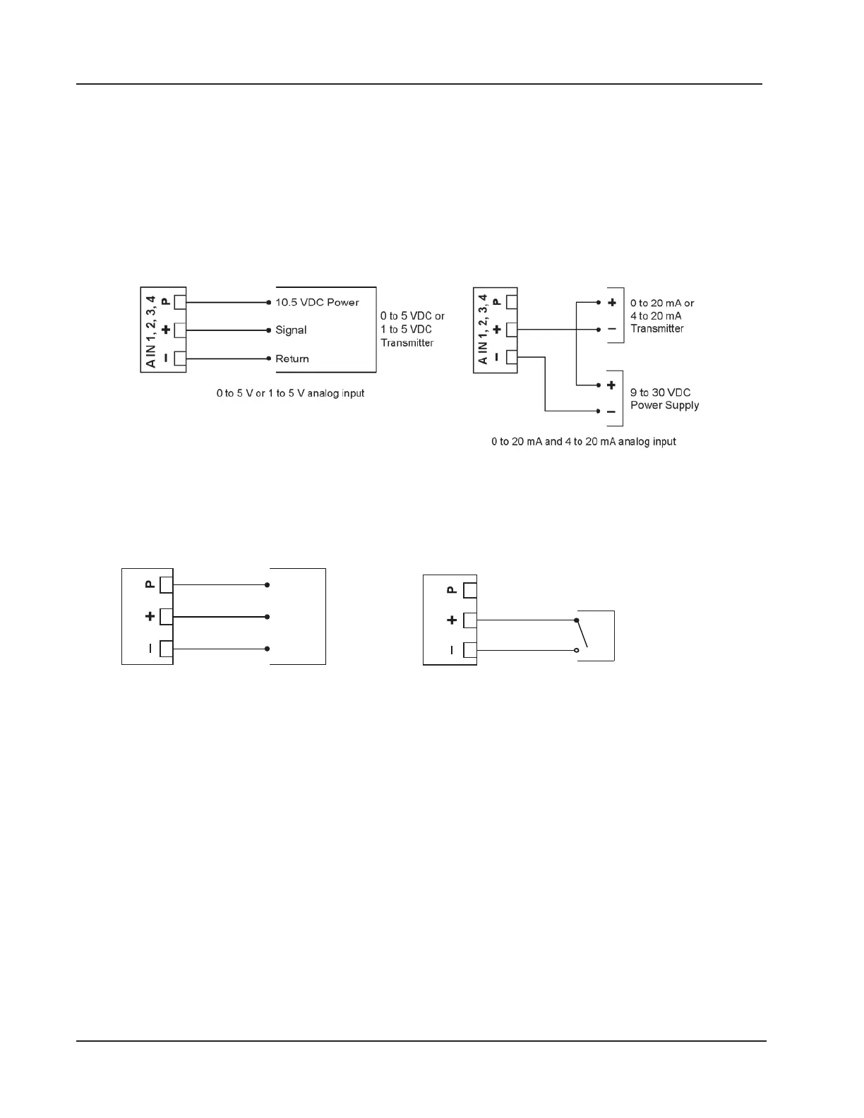
Analog Inputs
The analog inputs (Figure 3.7), which can be congured for a 0 to 5 V, 1 to 5 V, 0 to 20 mA or 4 to 20 mA signal, can
be used to receive readings from a pressure or temperature transmitter for use in any ow run. Alternatively, they can be
used to log measurements from any device with a 0 to 5 V, 1 to 5 V, 0 to 20 mA or 4 to 20 mA output. An on-board resis-
tor is automatically enabled when a current input is congured in the Scanner 3100 web interface. Therefore, no external
resistor is required for use with a current input.
The Scanner 3100 provides approximately 10 VDC at 20 mA for powering a 0 to 5 V or 1 to 5 V transmitter. It is not
suitable for powering a 4 to 20 mA transmitter. For reduced power consumption, disable analog inputs in the Scanner
3100 web interface when they are not in use.
Figure 3.7—Analog input
Pulse Inputs
Pulse inputs (Figure 3.8) provide an input for high-amplitude pulse (frequency) signals, such as signals from a turbine
meter equipped with a preamplier (shown at left) or signals from a positive displacement meter (shown at right).
Power
Out
GND
Input
TFM 1, 2, 3
Contact Closure
Input
Figure 3.8—Pulse input
60
Section 3 Scanner 3100 EFM