CAUTION Do not put the Scanner into operation until the valves are positioned properly so that pressure is
supplied to both sides of the MVT. For instructions on proper valve positions, see Placing the Scan-
ner into Operation, page 54.
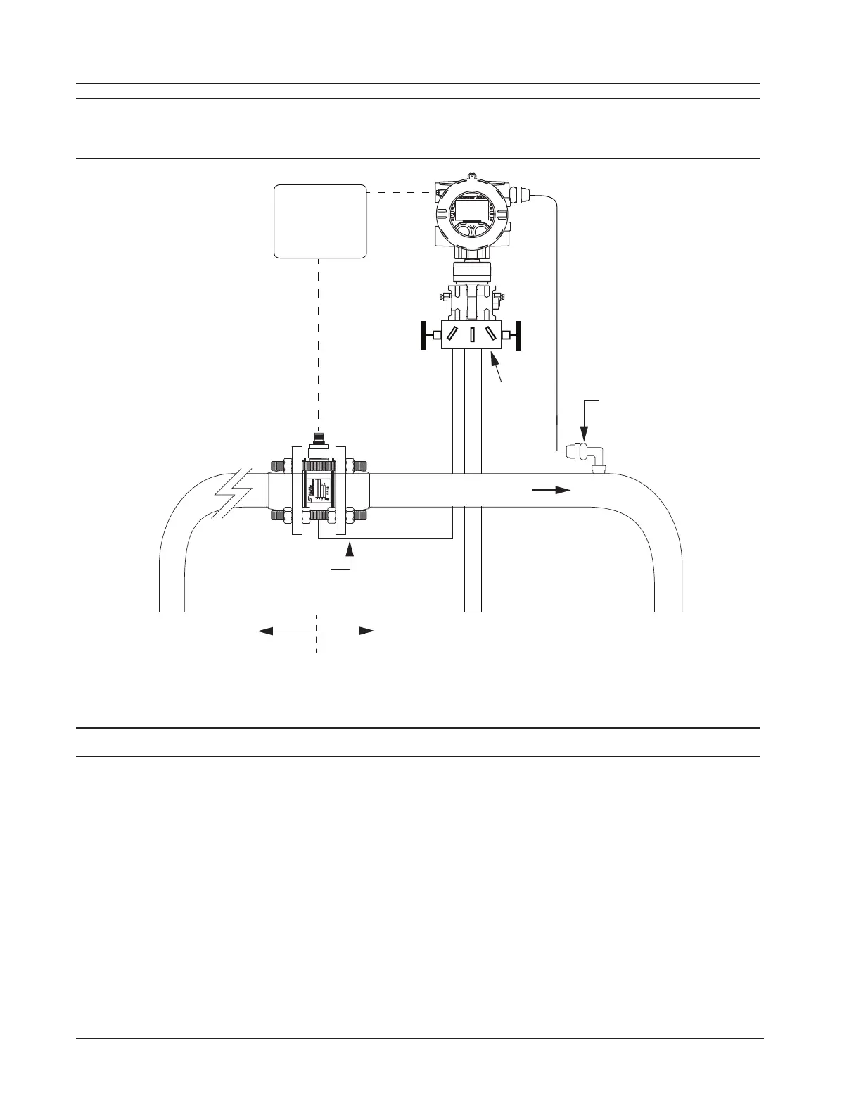
Static pressure input
(manifold equalizer
valve must remain open)
Manifold
RTD
assembly
10 pipe diameters
upstream
5 pipe diameters
Seal cable at point of
entry in accordance
with the relevant
code of practice
Flow
Figure 2.11—Remote-mount installation in an AGA 7 turbine meter run
Measuring Steam via a Differential Pressure Meter
Note Steam uid types are only supported for ow rate calculation methods using orice meters or cone meters.
Best Practices
The Scanner 3100 calculates steam ow in accordance with IF-97, AGA-3, and ISO-5167 industry standards. For opti-
mum performance, ensure that the installation complies with the following industry recommendations:
Condensate Pots
• A condensate pot for a small-volume transducer like the Scanner 3100 MVT can be a simple pipe tee, oriented so
that one port extends downward (into the cold leg), the opposite port extends upward and is closed by a pipe cap or
blowdown valve, and the tee extends horizontally into the hot leg.
• The pots should be the highest point in the system.
• The pots should be mounted at the same level, and one or both should be adjustable vertically to remove zero shifts in
the differential pressure measurement.
42
Section 2 Scanner 3100 EFM