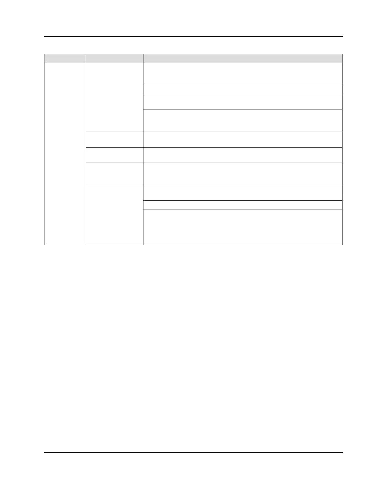
Table 2.2—Industry Standards for Meter Installation
Meter Type Standard Description
Turbine
Meter
AGA 7, Section 7 Installation of gas turbine meters to include ow direction, meter orientation,
meter run connections, internal surfaces, temperature well location, pressure
tap location, and ow conditioning
Illustrations of recommended installation congurations
Environmental considerations, the use of other devices to improve meter
performance, and precautionary measures
This specication applies to axial-ow turbine ow meters for measurement
of natural gas, typically 2-in. and larger bore diameter, in which the entire gas
stream ows through the meter rotor.
API MPMS Chapter
21.1, Section 1.7
Installation of electronic gas measurement devices and associated
communications, gauge/impulse lines, and cabling
API MPMS Chapter
21.1, Section 1.8
Requirements for calibrating and verifying the accuracy of electronic gas
measurement devices
API MPMS 5,
Section 3
Description of unique installation requirements and performance
characteristics of turbine meters in liquid hydrocarbon service (This section
does not apply to the measurement of two-phase uids.)
ISO 5167, Part 1 Installation of orice plates inserted into a circular cross-section conduit
running full
Limitation of pipe size and Reynolds number
ISO 5167 is applicable only to ow that remains subsonic throughout the
measuring section and where the uid can be considered single-phase. It is
not applicable to the measurement of pulsating ow. It does not cover the use
of orice plates in pipe sizes less than 50 mm (2 in.) or more than 1,000 mm
(39 in.), or for pipe Reynolds numbers below 5,000.
Measuring Natural Gas via a Differential Pressure Meter
Best Practices
For best measurement accuracy, ensure that the meter run complies with the following AGA 3 and ISO 5167 guidelines,
as applicable:
• Do not place unit near vents or bleed holes that discharge corrosive vapors or gases.
• Consider the orientation of the meter run when determining the best position for mounting the Scanner 3100.
– If the Scanner 3100 is mounted to a horizontal pipeline, make sure process connections are at the top of the line,
and mount the Scanner 3100 above the pressure connections at the pipe.
– If the Scanner 3100 is mounted to a vertical pipeline, install the sensor above the differential pressure source
connections, or install a condensate (drip) pot to prevent the accumulation of liquid in interconnecting tubes.
Slope all tubing upward at least 1 in./LF to avoid liquid entrapment.
• Mount the Scanner 3100 as near level as possible such that the operator has a clear view of the LCD and can access
the keypad easily when the enclosure cover is removed. The location should be as free from vibration as possible.
• Ensure the high port of the sensor (marked H) is connected to the upstream side of the meter run.
• Flow should remain subsonic throughout the measuring section and should be single phase.
• Pipe diameters (D) should be between 2 in. (50 mm) and 39 in. (1,000 mm) per ISO 5167; or greater than 2 in. (50
mm) per AGA 3.
• Pipe Reynolds numbers must be above 5,000.
• d (orice diameter) must be greater than or equal to 0.45 in. (11.5 mm).
37
Scanner 3100 EFM Section 2