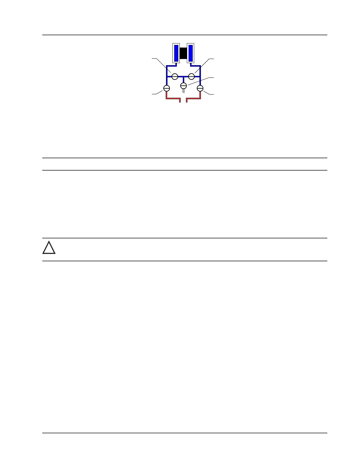
VENT
BYPASS/
BLOCK
EQUALIZER
BYPASS/
BLOCK
EQUALIZER
Figure 2.17—Valve positions for static pressure calibration
To verify the static pressure, perform the steps described in steps 6 through 12 above, except instead of clicking the Cali-
bration tab, click the Verication tab. You will be prompted to enter an applied value, and you will apply the same pres-
sure to the MVT, just as in the calibration process. The web interface will display a measured value and a percentage of
error. When you click Save, the measured values are written to memory.
Note Error is expressed as a percentage of the full scale of the MVT input range.
Differential Pressure Calibration and Verication
The static pressure and differential pressure inputs are calibrated and veried before the Scanner 3100 leaves the factory,
and recalibration in the eld may or may not be required. To comply with API standards for verication, “as found” read-
ings should be recorded at approximately 0, 50, and 100 percent of the operating pressure range, increasing, and at 80,
20 and 0 percent of the operating pressure range, decreasing. For example, the differential pressure measurements of a
200 in H2O sensor should be veried at 0 in. H2O, 100 in. H2O, 200 in. H2O, then at 160 in. H2O, 40 in. H2O, and 0 in.
H2O.
!
WARNING: Do not subject the Scanner 3100 to unnecessary shock or over-range pressure during mainte-
nance operations.
To calibrate the differential pressure:
1. Close the bypass valves to isolate the pressure below the manifold (Figure 2.18, page 54).
2. Open the equalizer valves and vent valve to purge the lines.
3. Close the high-pressure side equalizer valve, leaving the low side vented.
4. Connect a pressure simulator to the high-pressure side of the manifold.
5. Connect to the Scanner 3100 with the web interface.
6. Navigate to the Local I/O>DP:Diff Pres screen, click the Calibration tab, and click the Modify button. You will
be prompted to enter the Maintenance mode. See the Scanner 3100 Web Interface User Manual for complete
instructions.
7. Click the “Applied/As Left” eld, enter a known pressure.
8. Apply the same amount of pressure to the high side of the MVT using the simulator. and wait for the reading to be
acquired.
9. Click Accept to accept the reading and exit the dialog. The pressure read by the simulator will be displayed in the
As Found eld and the calculated error between the pressure applied and the pressure read will appear beside it.
10. Repeat steps 7 through 9 to enter multiple calibration points.
11. When all calibration points have been entered, click Save to apply the new calibration settings.
12. Exit the Maintenance mode.
53
Scanner 3100 EFM Section 2