Antenna Installation Options
Direct-Mount Antenna
Each Scanner 3100 wireless device is equipped with a wireless module (installed on an advanced communications circuit
board) and an explosion-proof coupler that threads into an enclosure port. Antennas and antenna cable are optionally
available.
The installation of the antenna coupler, antennas, and antenna cable must meet the requirements shown in Figure 2.4 and
Figure 2.5, page 32.
Remote-Mount Antenna for Pole Outside Diameters up to 2 Inches
The standard hardware supplied with Cameron’s remote-mount antenna can be used to mount the antenna to a pole with
an outside diameter of 2 in. or less. The supplied hardware includes two U-bolts, two toothed brackets, four lock washers
and four nuts.
Note If a 2-in. pipe with a 2 3/8-in. outside diameter is to be used, consider using Cameron’s 2-in. pipe mount hard-
ware kit.
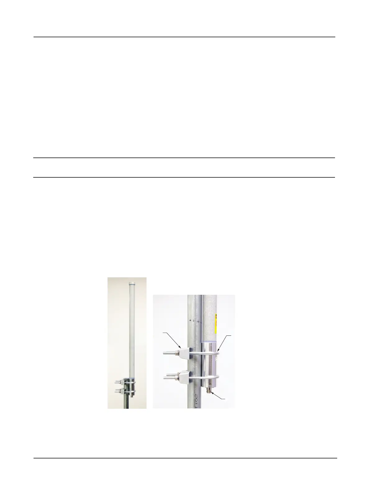
To install the antenna, reference Figure 2.7 while following the instructions below:
1. Position the antenna with the shiny metal base against a vertical pole and the capped end of the antenna vertical in
the air. Note the N-female cable connector at the bottom of the metal base for connecting antenna cable.
2. Position a U-bolt around the antenna and pole, placing the bend of the U-bolt against the antenna base.
3. Place a toothed bracket over the threaded legs of the U-bolt with the teeth facing the pole and slide the bracket
snugly against the pole.
4. Install a lock washer and a nut on each of the two U-bolt legs extending through the toothed bracket.
5. Repeat steps 2 through 4 to install the second U-bolt and toothed bracket to secure the base of the antenna.
6. Attach the antenna cable to the N-female cable connector at the bottom of the antenna.
Toothed
bracket
(2)
U-bolts (2)
N-female
Figure 2.7—Standard pole mount bracket (ts poles with an outside diameter of 2 in. or less)
34
Section 2 Scanner 3100 EFM