Section 5—Display and Keypad Operations
The Scanner 3100 display and keypad allows you to view the real-time measurements for up to 32 selected parameters,
5 at a time. By default, the parameters scroll continuously through the 5 elds provided (Figure 5.1). In a declassied or
safe area, you can use the keypad to manually pace the display. To access the keypad, remove the cover of the explosion-
proof enclosure.
!
WARNING: To prevent ignition of hazardous atmospheres, do not remove the cover while circuits are
alive. The Scanner 3100 poses no hazard when opened in a safe area.
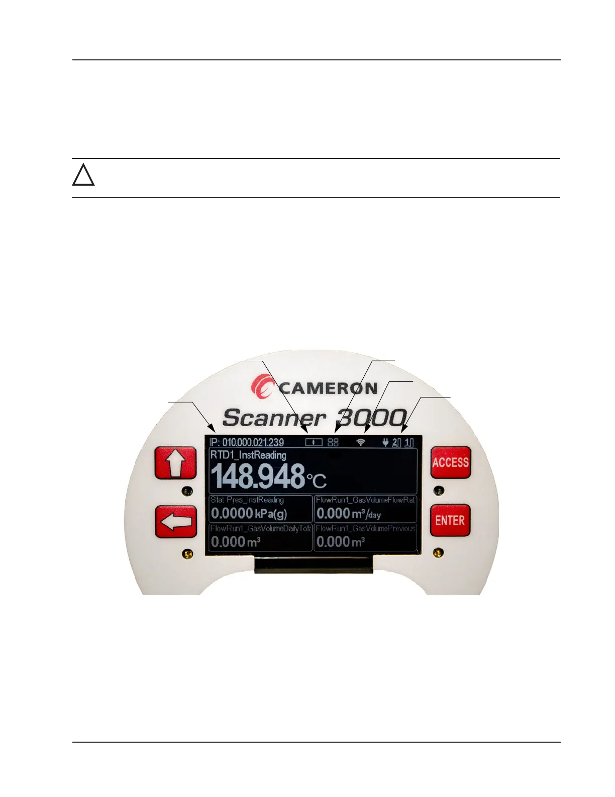
IP Address
The IP address used to connect with a Scanner 3100 via the web interface is displayed at the top of the LCD. The IP ad-
dress is assigned when a user connects to the device for the rst time using a computer or other browser-enabled device.
If no address appears in the display, check for a problem with the Ethernet connection.
Status Indicators (Glyphs)
When power is applied to the device, a row of pictorial status indicators or “glyphs” appears in the top right corner of the
LCD. You can use these glyphs to quickly assess the status of the LCD display, wireless connectivity, power connectiv-
ity, and battery capacity once you become acquainted with the symbols and their meanings (Figure 5.1 and Table 5.1—
Device Status Glyph Denitions, page 80).
Battery/Power
Indicators
Wireless Glyph
Keypad Glyph
IP Address
LCD Display Indicator
Figure 5.1—LCD display components
Additionally, glyphs indicating the parameter status appear to the left of the parameter reading. You can use these glyphs
to quickly identify the status of a parameter (fail, locked, high- or low-system alarm, etc.) See Table 5.2—Parameter Sta-
tus Glyph Denitions, page 81 for more information about the parameter status glyphs.
79
Scanner 3100 EFM Section 5