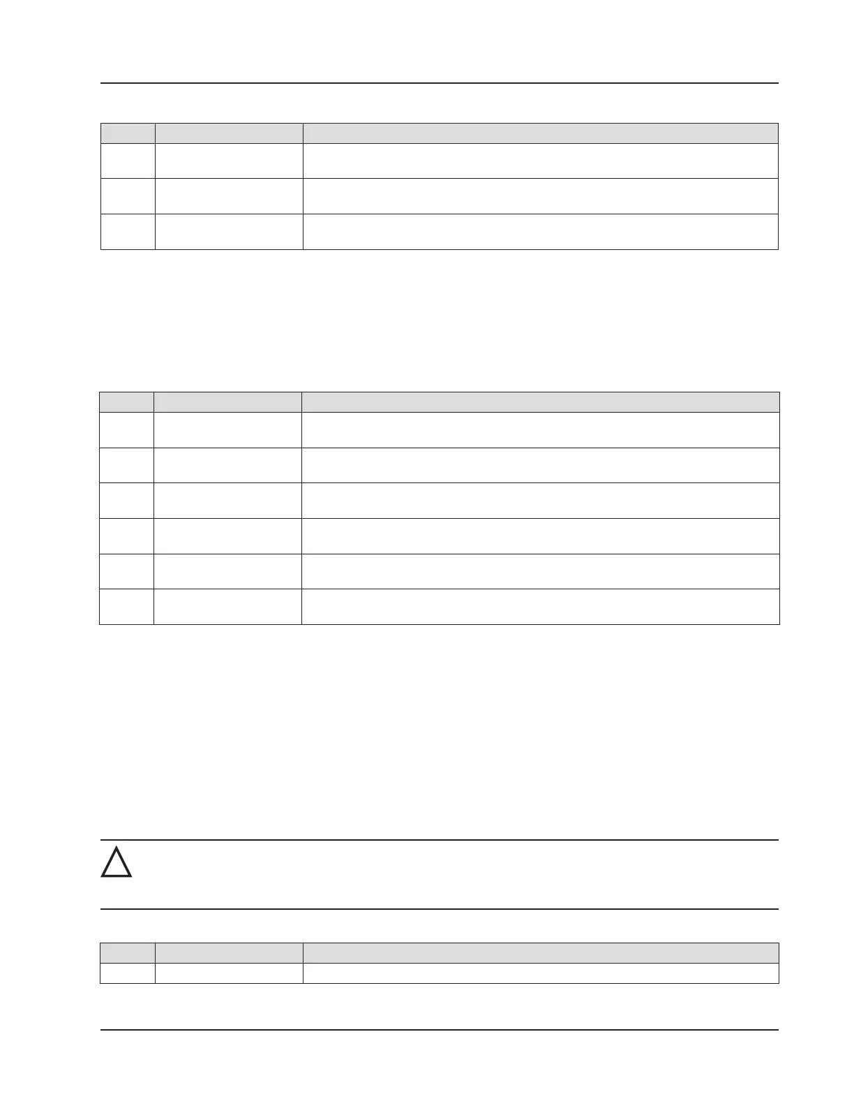
Table 7.2—Wireless Components
Qty. Part No. Description
1 50272960-30 Cable, Ethernet, 30 ft, for WiFi Communications Accessory for Multi-Scanner
Sites
2* 9A- 0111- 90 07 T Fuse, 5 amp, 5 × 20, Glass, for WiFi Communications Accessory for Multi-Scanner
Sites
2 9A-0142-9003T Assembly, Clamp and U-Bolt, 2-1/2 in., for WiFi Communications Accessory for
Multi-Scanner Sites
* Recommended spare part if WiFi Communications Accessory is in use
Table 7.3—RTD and Cable Assemblies
Select assemblies based on specic application.
Cable length and probe length are specied in the part number:
9A-21-XX-YY where XX is the cable length and YY is the probe length.
Available cable lengths: 5, 10, or 30 ft. Probe nominally adjustable up to 6 in. or 12 in.
Qty. Part No. Description
1 9A-21-05-06 Model 21 RTD, CSA Explosion-proof, 5-ft Cable, 7.625-in. Probe for 6-in.
Thermowell
1 9A-21-05-12 Model 21 RTD, CSA Explosion-proof 5-ft Cable, 11.625-in. Probe for 12-in.
Thermowell
1 9A-21-10-06 Model 21 RTD, CSA Explosion-proof 10-ft Cable, 7.625-in. Probe for 6-in.
Thermowell
1 9A-21-10-12 Model 21 RTD, CSA Explosion-proof 10-ft Cable, 11.625-in. Probe for 12-in.
Thermowell
1 9A-21-30-06 Model 21 RTD, CSA Explosion-proof 30-ft Cable, 7.625-in. Probe for 6-in.
Thermowell
1 9A-21-30 -12 Model 21 RTD, CSA Explosion-proof 30-ft Cable, 11.625-in. Probe for 12-in.
Thermowell
The thermowell dimensions listed above refer to the maximum “U” dimensions that a probe will fit with a plastic bushing.
Consult Cameron for sizing information if a union and nipple is to be used in place of a bushing. When using a bushing,
select the shortest probe possible for a compact installation and best strength.
Electronics Replacement
The Scanner 3100 contains two circuit board subassemblies (pre-assembled groupings of circuit boards and hardware),
a terminal board, and an optional advanced communications board (for support of wireless communications) that can be
replaced by a knowledgeable technician. For disassembly instructions, see the Scanner 3100 Service User Manual. Sub-
assemblies must be replaced without further disassembly.
Before attempting any repair work on a Scanner 3100, contact a Cameron technician to review the issues you are observ-
ing and determine if the problem requires hardware replacement.
!
CAUTION—EQUIPMENT DAMAGE RISK: Attempts to disassemble the Scanner 3100 in the eld for the
purpose of troubleshooting or repairs can damage the internals and cables beyond repair. Cameron does
not warranty damage resulting from eld replacement of Scanner 3100 parts.
Table 7.4—Scanner 3100 Circuit Board Replacements
Qty. Part Number Description
1 50279707 Display Subassembly, includes Hardware Kit and Coin Cell Battery
89
Scanner 3100 EFM Section 7