Output Wiring
Analog (4 to 20 mA) Outputs
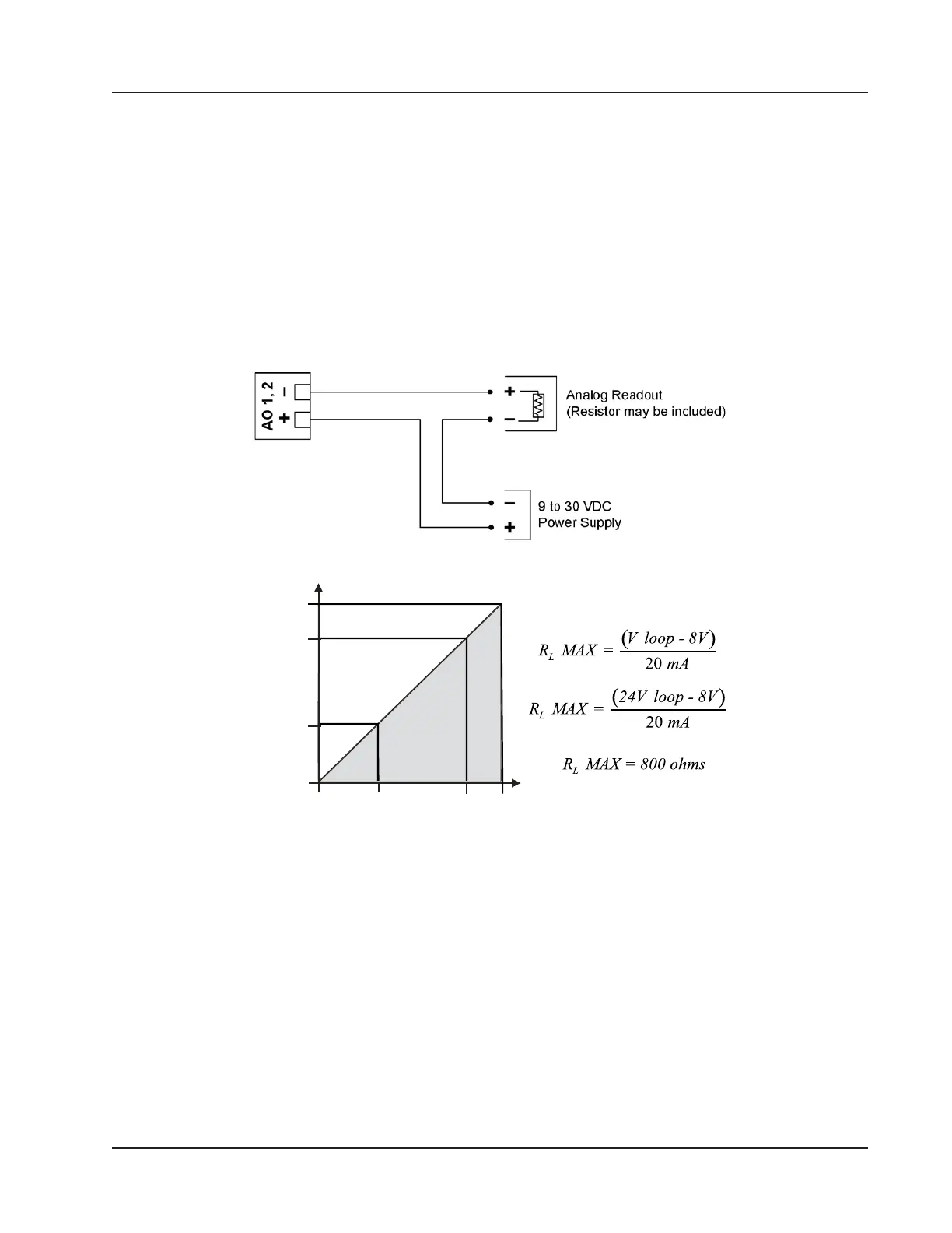
The 4 to 20 mA output (Figure 3.12) provides a linear current output that can be congured to represent any parameter
in the holding registers using the Scanner 3100 web interface. This output requires a two-conductor cable connected to
a 9 to 30 VDC power supply (voltage required is dependent on loop resistance) and a current readout device located in
the remote location. The analog outputs are electrically isolated from each other and from the main electronics. See the
Scanner 3100 Web Interface User Manual for information on conguring and calibrating zero and full-scale values.
The load resistance vs. loop supply voltage graph below shows the minimum voltage required to power the instrument
for a given loop resistance. In addition, the mathematical relationship between loop voltage and load resistance is given.
For example, if a power supply voltage of 24 volts is available to power the current loop, the maximum load resistance
would be 800 ohms.
1100
800
200
0
8 12 24 30
LOOP SUPPLY VOLTAGE (VDC)
LOAD RESISTANCE (OHMS)
OPERATING
REGION
Figure 3.12—Analog (4 to 20 mA) output
63
Scanner 3100 EFM Section 3