• β (diameter ratio) must be greater than or equal to 0.1 and less than or equal to 0.75.
• Gauge lines should be of uniform internal diameter and constructed of material compatible with the uid being
measured. For most applications, the bore should be no smaller than 1/4 in. (6 mm) and preferably, 3/8 in. (10
mm) in diameter. The internal diameter should not exceed 1 in. (25 mm). If high-temperature uids are likely to be
encountered, make sure the measuring tube used is rated for the anticipated temperature range.
• Gauge line length should be minimized to help prevent pulsation-induced errors.
• Gauge lines should slope downward to the meter at a minimum of 1 in. per foot.
• If gauge lines must slope in more than one direction, do not allow more than one bend and install a liquid or gas
trap, as applicable. A liquid trap should be installed at the lowest point in a gas service installation.
• Gauge lines should be supported to prevent sag and vibration.
• Where pulsation is anticipated, full-port manifold valves with a nominal internal diameter consistent with the gauge
lines are recommended.
If the Scanner 3100 is mounted to a cone meter, consider the following best practices as well:
• Position the cone meter so that there are 0 to 5 diameters of straight pipe upstream of the meter and 0 to 3 diameters
of straight pipe downstream of the meter.
• Install the meter so that the static pressure tap is upstream of the differential pressure tap. The high side of the
integral Scanner 3100 sensor must also be situated upstream.
• Install shutoff valves directly on the pressure taps. Choose a shutoff valve that is rated for the ambient temperatures of
the location and the operating pressure of the pipe in which it will be installed, and suitable for use with dangerous or
corrosive uids or gases, if applicable. The valves must not affect the transmission of the differential pressure signal.
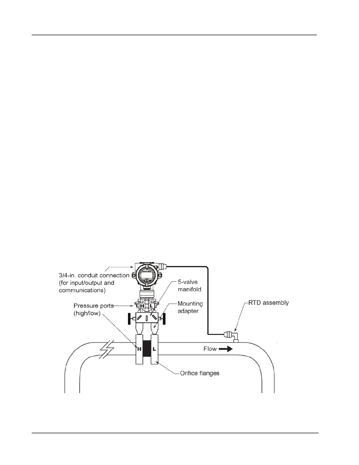
Direct Mount to Orice Meter or Cone Meter
A Scanner 3100 can be mounted directly to an orice meter or cone meter for gas measurement. The setup of the meter
run and plumbing congurations can vary widely, depending upon the challenges existing on location. Figure 2.9 shows
a typical direct-mount installation.
Figure 2.9—Direct-mount installation in an orice meter run. The direct-mount method can be used with a cone meter as
well.
38
Section 2 Scanner 3100 EFM