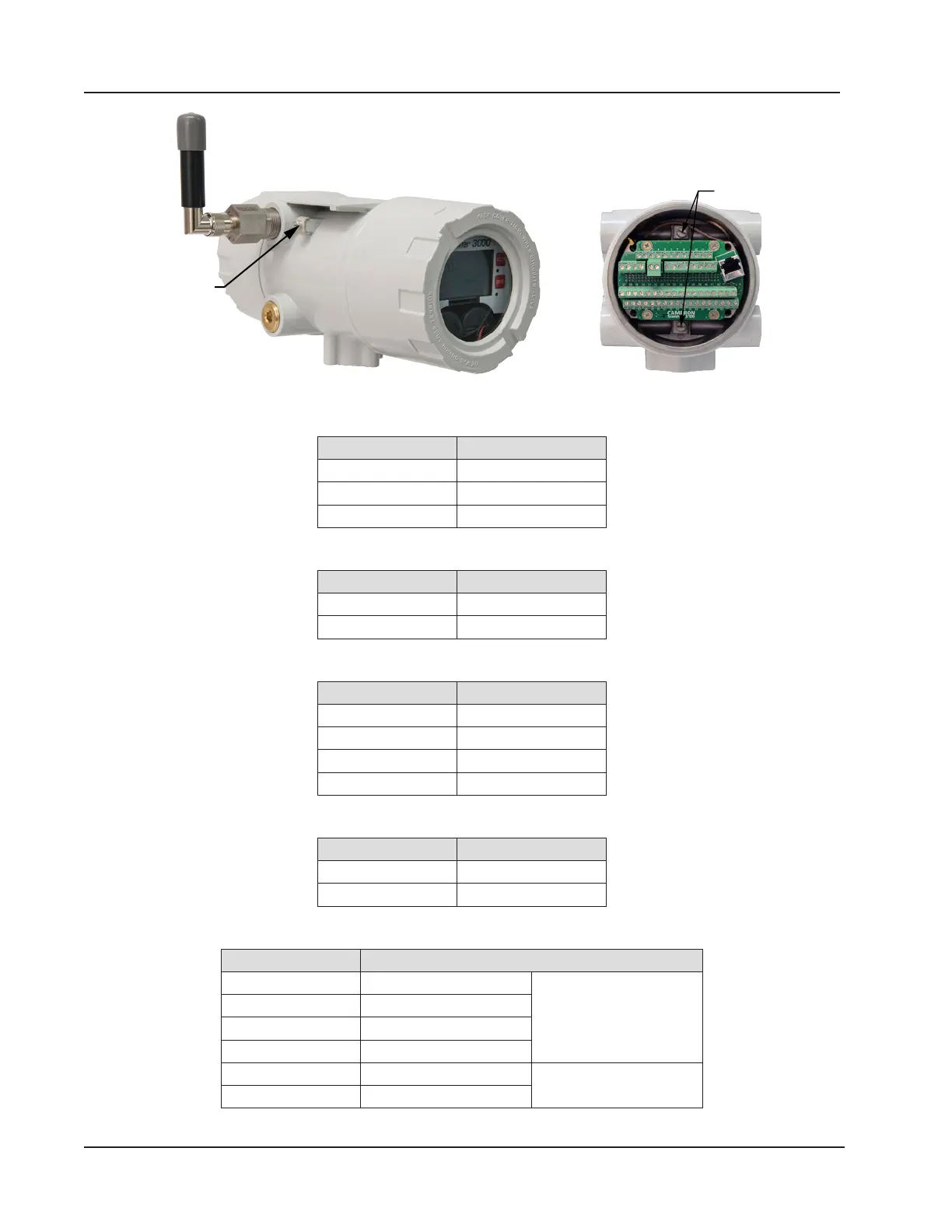
Ground screw
Figure 3.2—External and internal ground screw locations
c. Connect the owmeter input wiring to TFM 1, TFM 2, or TFM 3, as required.
Terminal Block Terminals
TFM 1 7, 8, 9
TFM 2 39, 40, 41
TFM 3 21, 22, 23
d. Connect the process temperature input wiring to RTD 1 or RTD 2, as required.
Terminal Block Terminals
RTD 1 13, 14, 15, 16
RTD 2 27, 28, 29, 30
e. Connect analog input wiring to A IN 1, A IN 2, A IN 3 or A IN 4, as required.
Terminal Block Terminals
A IN 1 1, 2 , 3
A IN 2 4, 5, 6
A IN 3 45, 46, 47
A IN 4 48, 49, 50
f. Connect analog output wiring to AO 1 or AO 2, as required.
Terminal Block Terminals
AO 1 19, 20
AO 2 37, 38
g. Connect digital input/output wiring to DIO 1, DIO 2, DIO 3 or DIO 4, as required.
Terminal Block Terminals
DIO 1 31, 32, 33, 54 (COM) Use 54 (COM) only with
DIOs 1, 2, 3 and 4.
DIO 2 34, 35, 36, 54 (COM)
DIO 3 51, 52, 53, 54 (COM)
DIO 4 54 (COM), 55, 56, 57
DIO 5 24, 25 (COM) Use 25 (COM) only with
DIOs 5 and 6.
DIO 6 25 (COM), 26
56
Section 3 Scanner 3100 EFM