1. Verify that the meter is properly installed in the ow line (per manufacturer’s instructions).
2. Mount the Scanner 3100 to a 2-in. pipe using the mounting bosses on the side of the enclosure and a Cameron pole
mount kit. See Pole-Mounting the Scanner 3100, page 30 for detailed mounting instructions.
3. Bolt a 5-valve ange-by-NPT manifold (as recommended by Cameron) to the Scanner 3100 MVT sensor.
a. Locate the H and L markings on the integral MVT sensor body and position the MVT/manifold assembly so
that the upstream side of the ow line can easily be connected to the sensor’s “High” port and the downstream
side of the ow line can be connected to the sensor’s “Low” port. The Scanner 3100 enclosure can be rotated to
face the desired direction.
b. Position the manifold so that all valves are accessible from the front of the instrument.
4. Install tubing and ttings to connect the Scanner 3100 and manifold assembly to the differential pressure meter,
sloping the gauge lines downward to the meter at a minimum of one inch per foot. Use a suitable compound or tape
on all threaded process connections.
CAUTION Do not use Teon tape on the threads of the union, adapter, or pipe plugs that may be installed in
the enclosure. Use of Teon tape will void the explosion-proof rating of the instrument.
5. Install the RTD assembly in the thermowell. Route the RTD assembly cable through a conduit opening in the top
of the Scanner 3100 to connect to the terminal board. A wiring diagram for the RTD assembly is provided in Figure
3.6, page 59. For hazardous areas, review Hazardous Area Precautions, page 27.
6. Route any additional inputs/outputs or COM connections, etc. through a conduit opening in the top of the Scanner
3100. For hazardous areas, review Hazardous Area Precautions, page 27.
7. Perform a manifold leak test as described in Performing a Manifold Leak Test, page 51.
8. Verify the zero offset (if required) and other calibration points (if desired). See the Scanner 3100 Web Interface User
Manual for complete instructions. See also Zero Offset (Static Pressure or Differential Pressure), page 51, Differ-
ential Pressure Calibration and Verication, page 53, and Static Pressure Calibration and Verication, page 52.
CAUTION Do not put the Scanner into operation until the valves are positioned properly so that pressure is
supplied to both sides of the MVT. For instructions on proper valve positions, see Placing the Scan-
ner into Operation, page 54.
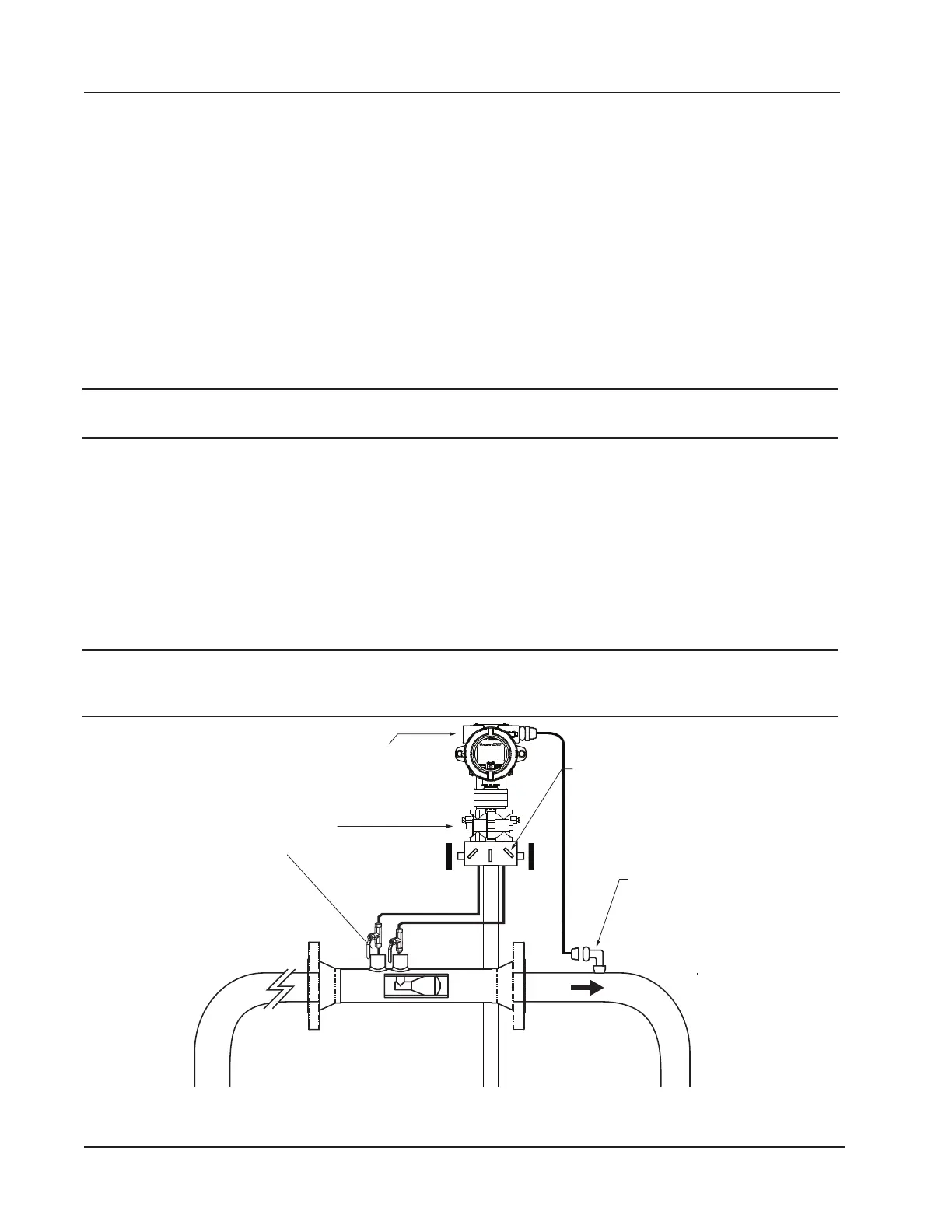
Flow
Manifold
Pressure ports
(high/low)
L
H
H
L
3/4-in. conduit connection
(for input/output and
communications)
Figure 2.10—Remote-mount gas cone meter run installation. The remote-mount method can be used with an orice meter
as well.
40
Section 2 Scanner 3100 EFM