COPYRIGHT © 1998 CANON INC. CANON PC400/420/430,FC200/220 REV.0 JAN.1998 PRINTED IN JAPAN (IMPRIME AU JAPON)
CHAPTER 10 TROUBLESHOOTING
10-9
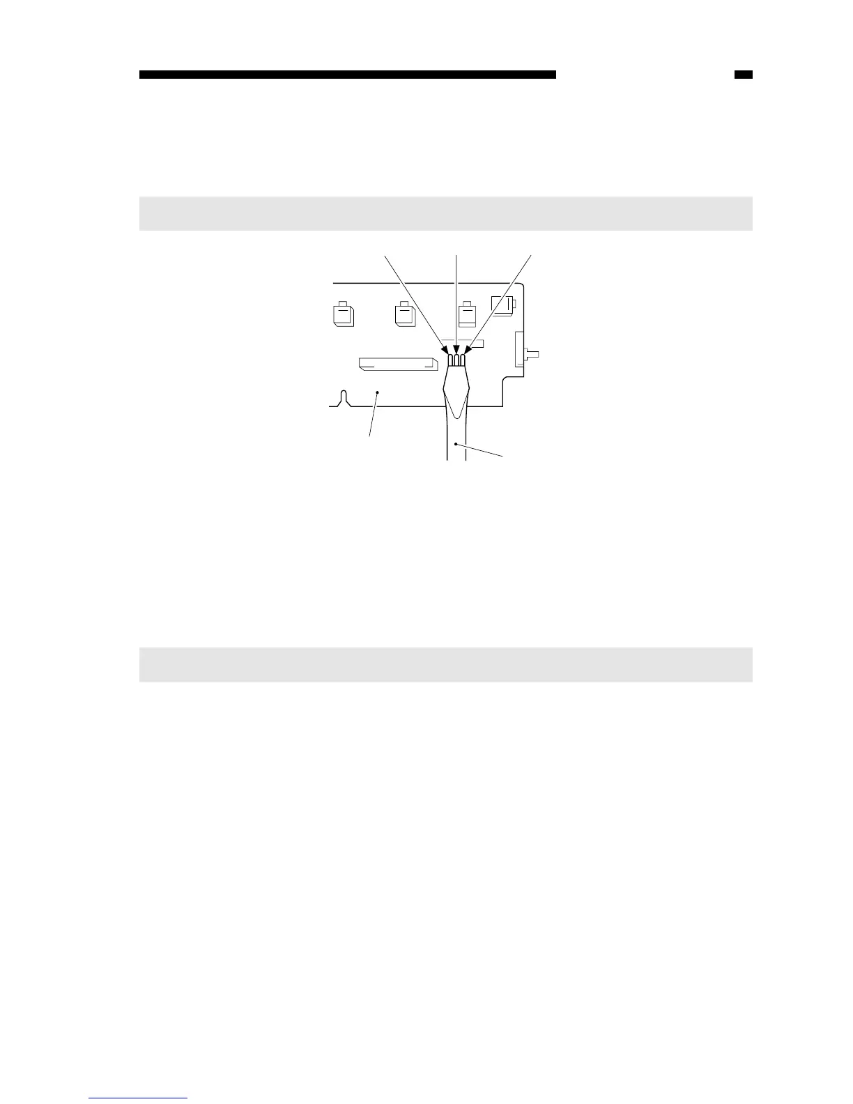
Figure 10-204B
6) While keeping the condition in step 5), switch the copier ON.
• ‘0’ is displayed, the scanning lamp goes ON, and the main motor starts to rotate.
7) Stop shorting the jumper wires.
8) Set the digital multimeter to the 20V DC range, and turn VR602 (AE offset adjust-
ment) until the voltage between the anode side of the diode (D606; +) and JP607
(GND) is 4.0 ±0.1 V.
Notes:
You must use a Digital Multimeter when making adjustments in steps 8) and 10).
5) Short the three jumper wires (JP604, JP605, JP607) on the control panel PCB at the
same time using a screwdriver.
Caution:
Take adequate care not to short wires other than those specified.