EasyManua.ls Logo

Canon PC430 - Outline of Electrical Circuit

Canon PC430
306 pages
Print Icon
To Next Page IconTo Next Page
To Previous Page IconTo Previous Page
Loading...
COPYRIGHT © 1998 CANON INC. CANON PC400/420/430,FC200/220 REV.0 JAN.1998 PRINTED IN JAPAN (IMPRIME AU JAPON)
2-2
CHAPTER 2 BASIC OPERATION
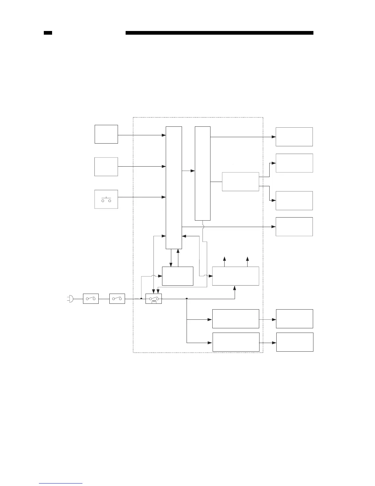
B. Outline of Electrical Circuit
The copier’s main electrical mechanisms are controlled by the microprocessor on
the DC controller/DC power supply PCB. According to the program stored in advance,
the microprocessor reads input signals from the control keys, and generates signals to
drive such loads as motors, solenoids, and lamps, as necessary.
Q101
TH1
Q
Photointerrupter
Thermistor
RelayDoor
switch
High-voltage
transformer
DC load
Sub power
supply circuit
DC power
supply PCB
AC driver AC load
Developing
cylinder
Primary/Transfer
charging roller
Display
+DC5V
+DC24V
+DC5V
Scanning lamp
Main motor
Solenoid
Heater
DC controller/DC power supply PCB
Copyboard position
sensor
Delivery sensor
Pick-up sensor
Fixing heater
temperature sensor
Power switch
Control key
Delivery
door
switch
Microprocessor
Driver assembly
Driver Scanning lamp
Figure 2-101B

Table of Contents

Other manuals for Canon PC430

Related product manuals