COPYRIGHT © 1998 CANON INC. CANON PC400/420/430,FC200/220 REV.0 JAN.1998 PRINTED IN JAPAN (IMPRIME AU JAPON)
2-6
CHAPTER 2 BASIC OPERATION
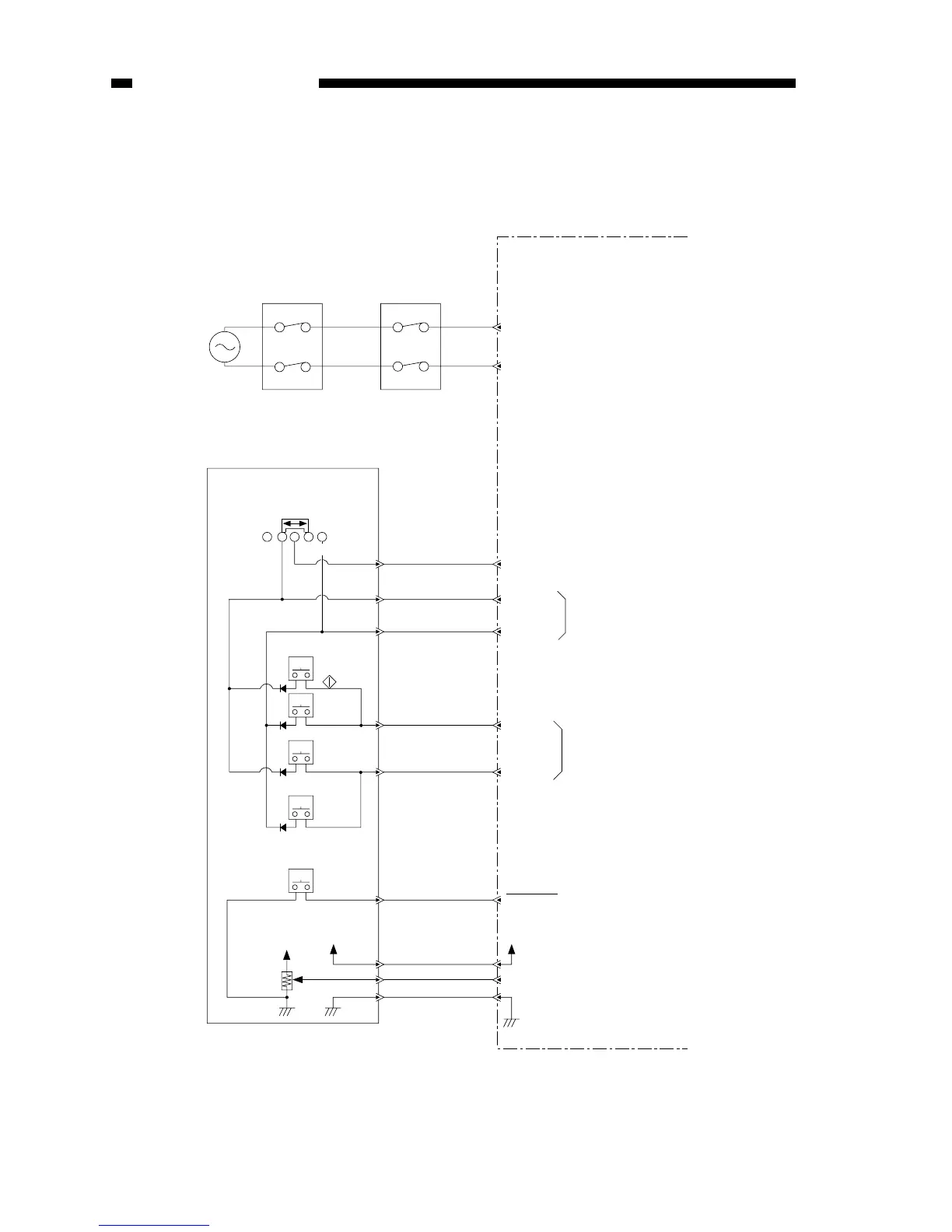
E. Inputs to DC Controller
1. Inputs to DC Controller (1/2)
KEYR 2
AC power
supply
Delivery door switch
SW2
Door switch
SW1
DC controller/DC power supply PCB
J104
Press on any key or density
correction switch allows input
of oscillation signal.
(PC420/430/FC220 only)
Oscillation signal (output;
PC420/430/FC220 only)
Turning density adjustment dial varies
voltage. (turn to darken brings it closer to 0V)
Note: The pin No. in parentheses refers
to the PC400/FC200.
PWSON
Control panel PCB
Density
adjustment
dial/lever
Power switch
Density
correction
switch
(PC420/430/
FC220)
Oscillation signal (output)DGT 2
KEYR 3
DGT 0
DGT 1
5V
J202-1
J601
-21(-16)
J601-13(-8)
J601-22(-17)
+5V
+5V
VR601
SW604
SW605
(AE)
SW603
(C/S)
(bottom: lightens) (top: darkens)
SW601
( )
SW602
( )
+
J202
-2
J601
-14(-10)
J202
-9(-8)
J601
-15
J202
-8
J601
-19
J202
-4
J601
-1
J202
-22
J601
-2
J202
-21
J601
-20(-15)
J202
-3
SW606
0 1 2
J103
J202-10
When ‘0’, power switch goes ON.