COPYRIGHT © 1998 CANON INC. CANON PC400/420/430,FC200/220 REV.0 JAN.1998 PRINTED IN JAPAN (IMPRIME AU JAPON)
CHAPTER 3 EXPOSURE SYSTEM
3-7
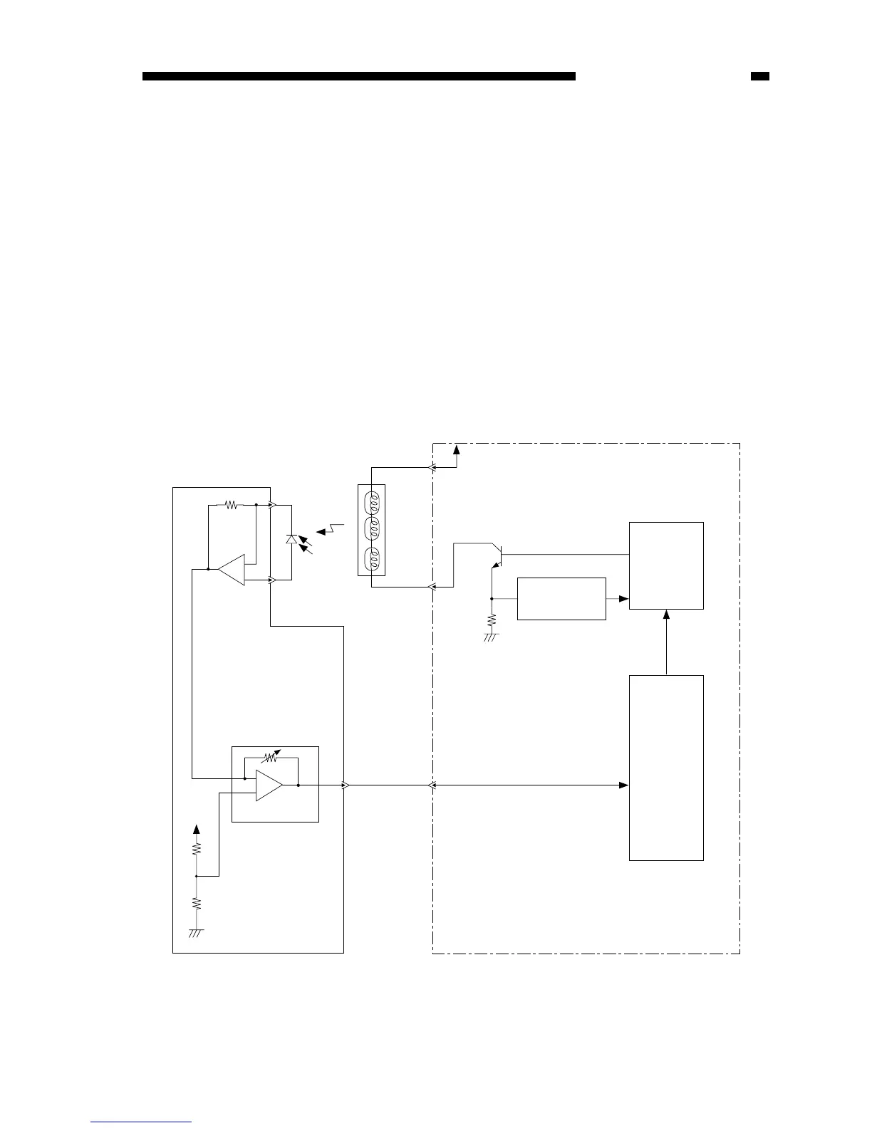
II. Controlling the Scanning Lamp
A. Outline
Figure 3-201A shows the circuit that controls the scanning lamp (fuse lamp), and the
circuit has the following functions:
• Turns the scanning lamp ON and OFF.
• Controls the intensity of the scanning lamp.
An intensity sensor (PD601) is provided to ensure that the original will be illuminated
after the intensity of the scanning lamp has stabilized.
The intensity of the scanning lamp is checked by the lamp intensity detection signal
(LID) to make sure that the intensity has reached the specified value.
In addition, a rush current protection circuit is provided to prevent rush current
occurring when the lamp turns on.
FIgure 3-201A
Scanning lamp
(LA1-LA8)
J621
-4
-3
(-1)
+
-
+
-
Intensity sensor
(PD601)
VR604
5V
Control panel PCB
Amplifier circuit
J601
-10
(-5)
J108-2
+24VU
Q143
Lamp
driver
circuit
Rush current
protection circuit
Lamp ON
signal
(LAPWM)
Lamp intensity sensor signal (LID)
The number within parentheses represents the PC400/FC200.
J202
-13
DC controller/DC power supply PCB
Microprocessor
J108-1