CHAPTER 6 ARRANGEMENT AND FUNCTIONS OF ELECTRICAL PARTS
6-5
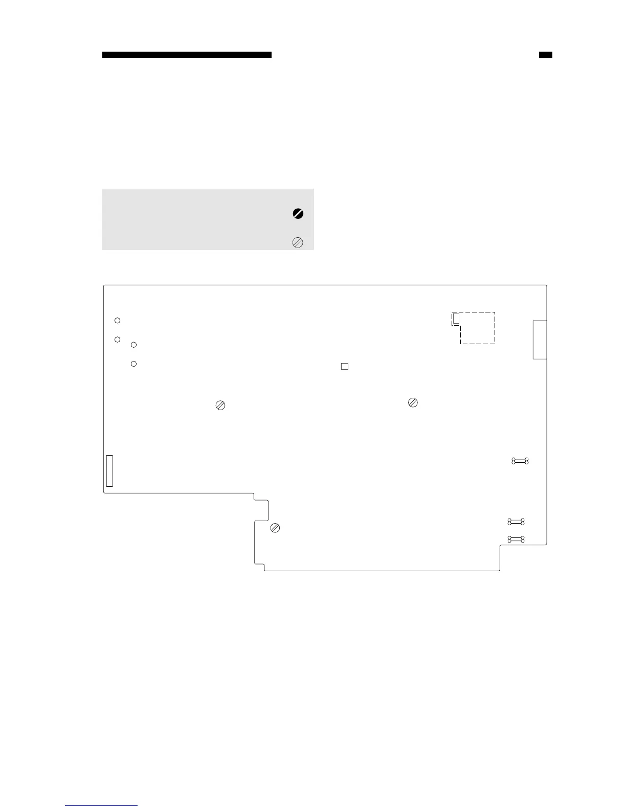
E. Variable Resistors (VR) and Check Pins by PCB
Of the variable resistors (VR) and check pins used in the copier, those used in the
field are discussed herein.
Do not touch those VRs and check pins not discussed herein; they are for factory
use only and require special tools and high precision for adjustment.
Note:
1. VRs that may be used
in the field..............................
2. VRs that must not be
used in the field. ....................
1. DC Controller/DC Power Supply PCB