COPYRIGHT © 1998 CANON INC. CANON PC400/420/430,FC200/220 REV.0 JAN.1998 PRINTED IN JAPAN (IMPRIME AU JAPON)
4-12
CHPTER 4 IMAGE FORMATION SYSTEM
The microprocessor varies the pulse width of the transfer DC bias control command
(DCTPWM) according to the internal resistance of the transfer charging roller affected
by the surrounding environment, thereby controlling the negative DC bias.
If an overcurrent occurs in the output side of the transformer (T107) because of
changes in the environment, the current limiter circuit exerts control so that no current
larger than the specified value will flow.
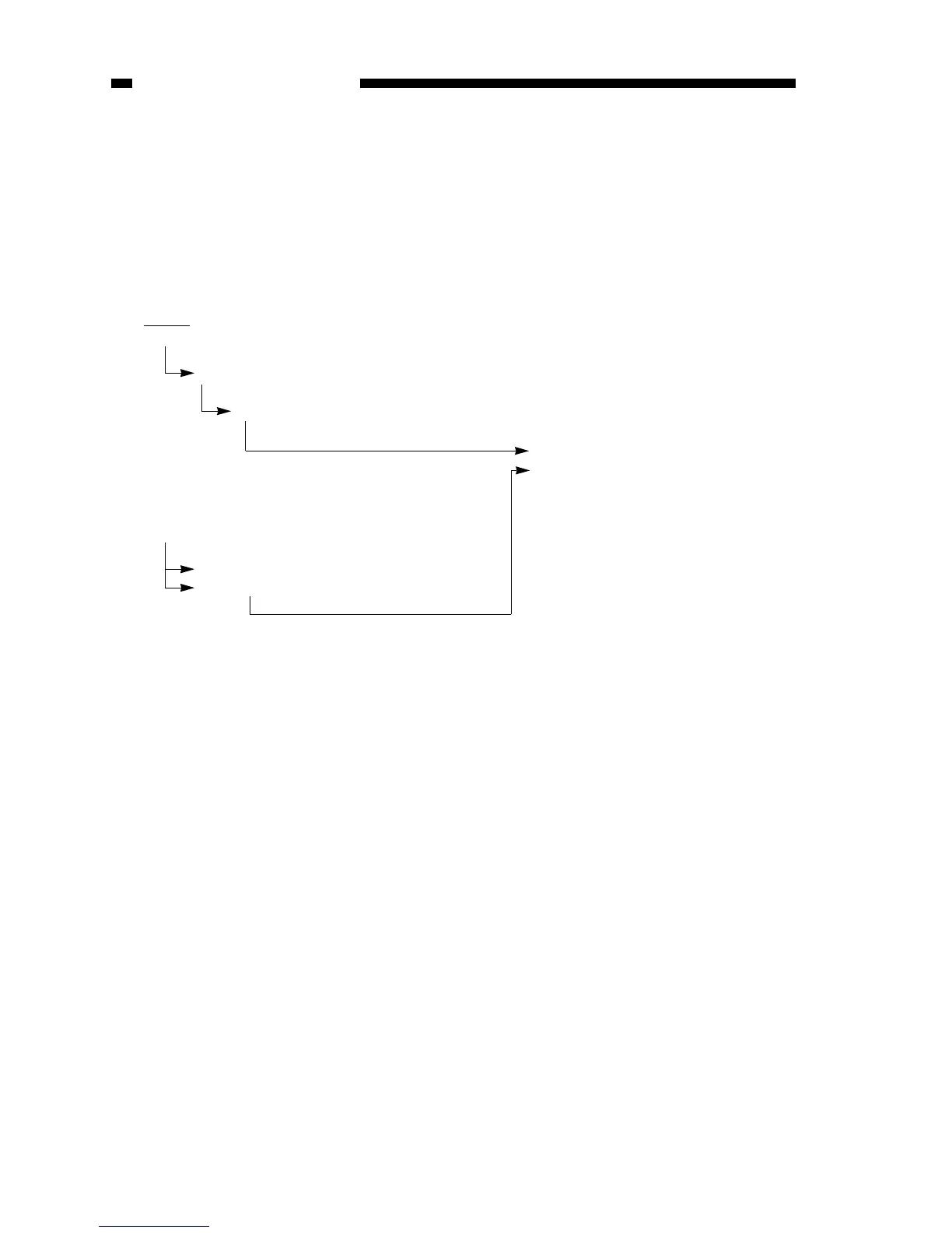
c. Operations in Cleaning Mode
TREV=0
Positive bias control circuit goes ON.
Multiplier/rectifier circuit goes ON.
Cleaning mode is selected, apply-
ing a positive DC bias to the
transfer charging roller.
HVTDC=0, DCTPWM=0
Oscillation circuit goes OFF.
Pulse/DC converter circuit goes OFF.