EasyManua.ls Logo

Canworld CDE360-2S0R7 - Page 100

Default Icon
267 pages
Print Icon
To Next Page IconTo Next Page
To Previous Page IconTo Previous Page
Loading...
CDE360 Vector Control AC Drive Chapter 6 Parameters Description
-87-
A0.08
Range: 0.00~b0.00
Default: 0.00
Main frequency A
Unit: Hz
It displays the setting of main frequency A.
A0.09
Range: 0.00~b0.00
Default: 0.00
Auxiliary
frequency B
Unit: Hz
It displays the setting of auxiliary frequency B.
A0.10
Range: 0~65535
Default: 0
AC drive status
word
It displays the drive status. The means of every bit is below:
Bits
0
1
Bit 0
No ready
Ready
Bit 1
Stop
Running
Bit 2
No fault
Fault
Bit 3
No warning
Warning
Bit 4
Forward
Reverse
Bit 5
00: Keypad control 01: Terminal control
10: Communication control 11: Invalid value
Bit 6
Bit 7
No signal of run enable
Received a signal of run enable
Bit 8
Drive control
Bypass control
Bit 9
Running frequency have not
reached setting frequency
Running frequency have reached
setting frequency
Bit 10
00: Constant speed 01: Accelerate speed
10: Decelerate speed 11: Invalid value
Bit 11
Bit 12
Common mode
JOG mode
Bit 13
Not in tuning
In tuning
Bit 14
No zero-speed output
Zero-speed output
Bit 15
Reserve
A0.11
Range: -10.00~10.00
Default: 0.00
AI1 voltage
Unit: V
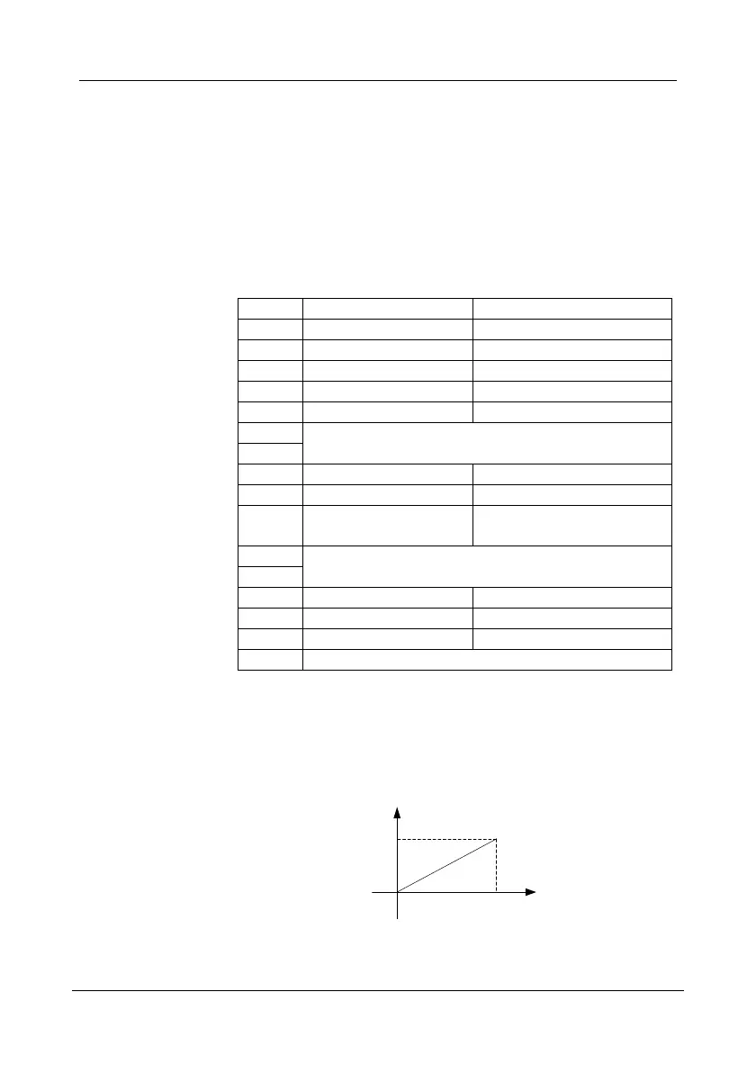
It display AI1 voltage. If the AI1 is analog current input mode then system
will convert current value to voltage value.
0mA equal to 0V, 20mA equal to 10V.
0
20 mA
10 V
Figure 6- 1 Analog current mode convert to analog voltage mode

Table of Contents

Related product manuals