Do you have a question about the Canworld CDE360-2S0R7 and is the answer not in the manual?
Details crucial safety warnings and precautions before and during installation.
Covers essential general precautions for safe operation, grounding, and motor handling.
Details all fault types, their codes, and associated descriptions.
Outlines fundamental parameters for AC drive operation and configuration.
Describes parameters related to the AC drive's acceleration, deceleration, and start/stop logic.
Explains how to configure the main and auxiliary frequency sources for the AC drive.
Details the functions and configurations for all digital input terminals.
Describes the functions and configurations for all digital output terminals.
Lists parameters for configuring and calibrating analog input signals.
Details parameters for configuring and calibrating analog output signals.
Explains the configuration parameters for pulse input and output functions.
Outlines parameters for controlling motor operation modes and characteristics.
Details parameters for configuring motor-specific properties like resistance and inductance.
Explains parameters for tuning the speed control loop (ASR) for optimal performance.
Covers parameters for setting and controlling motor torque.
Outlines all parameters related to the PID control loop configuration and tuning.
Details all protection parameters, including overvoltage, overcurrent, and motor protection.
Lists essential system parameters like password, display settings, and function code lock.
Provides a comprehensive list of faults, their possible causes, and corresponding solutions.
| Category | DC Drives |
|---|---|
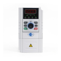
| Model | CDE360-2S0R7 |
| Output Power | 0.75kW |
| Enclosure Rating | IP20 |
| Communication Interface | RS485 |
| Operating Temperature | 40°C |
| Storage Temperature | -20°C |
| Cooling Method | Forced Air |
| Protection Features | Overcurrent, Overvoltage, Undervoltage, Overtemperature, Short circuit |
| Control Method | Closed-loop vector control |