EasyManua.ls Logo

Canworld CDE360-2S0R7 - Chapter 5 Parameter List Table

Default Icon
267 pages
Print Icon
To Next Page IconTo Next Page
To Previous Page IconTo Previous Page
Loading...
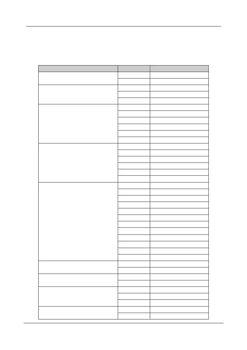
CDE360 Vector Control AC Drive Chapter 5 Parameter List Table
-45-
Chapter 5 Parameter List Table
The symbols in the parameter list table are described as follows:
”: The parameter cannot be modified when the AC drive is in the running state.
Classification
Function Code
Description
Group A
Monitor and Diagnostics
A0
Monitor
A1
Fault & Diagnostics
Group b
Basic Running Parameters
b0
Basic Parameters
b1
Run & Stop Logic
b2
Frequency Source
Group C
Input and Output Terminals
C0
Digital Input
C1
Digital Output
C2
Analog Input
C3
Analog Output
C4
Pulse Input/Output
C5
Virtual Digital Input/Output
Group d
Motor Control
d0
Motor Control
d1
Motor Parameters
d2
Speed Control
d3
Torque Control
d5
Motor 2 Parameters
d6
Motor 2 Speed Control
Group E
Expanding Application Functions
E0
JOG
E1
Skip Frequency
E2
Multi-Reference
E3
Simple PLC
E4
Acc & Dec Time
E5
PID
E6
Multi-Pump Control
E7
Swing Frequency
E8
Droop Control
E9
Power Loss Ride Through
EA
External Brake
Eb
Supervision
Group F
Protection and Reset
F0
Protection
F1
Auto Reset
Group H
System Parameters and Analog Calibration
H0
System Parameters
H1
AI/AO Calibration
Group L
Communication Setting
L0
Communication Setting
L1
Point-point Communication
L2
Encoder Setting
Group P
User-defined and Debug Parameters
P0
User-defined Parameters
P1
Debug Parameters

Table of Contents

Related product manuals