CDE360 Vector Control AC Drive Chapter 5 Parameter List Table
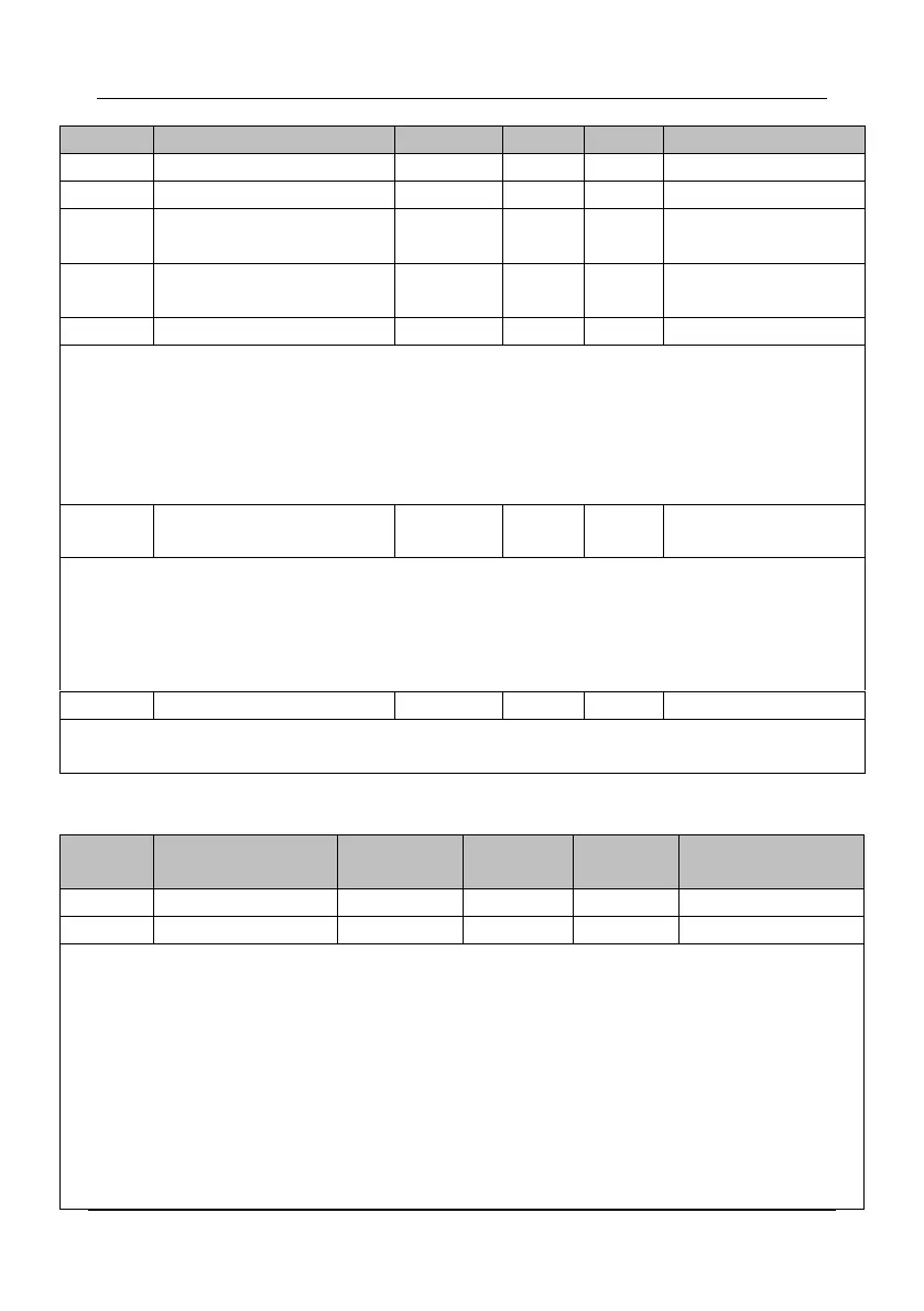
Auxiliary frequency source B
Range of auxiliary frequency
source B
Offset frequency for A and B
operation
Frequency source selection
Unit's digit (Frequency source selection)
0: Main frequency source A
1: A and B operation
(operation relationship determined by ten's digit)
2: Switchover between A and B
3: Switchover between A and "A and B operation"
4: Switchover between B and "A and B operation"
Ten's digit (A and B operation relationship)
Binding command source to
frequency source
Unit's digit (Binding the frequency source together with Keypad control source)
0: No binding
1: b2.01+UP/DOWN
6: Multi-reference
7: PLC
Ten's digit (Binding the frequency source together with Terminal control source)
Hundred's digit (Binding the frequency source together with Communication control source)
All the parameters with ‘Hz’ unit will change following b2.07. Such as b0.09(50.00Hz) will change to
500.0Hz when set b2.07 from 1 to 2.
C0 Digital Input
0: No function
1: Forward JOG(FJOG)
2: Reverse JOG(RJOG)
3: Forward RUN (FWD)
4: Reverse RUN (REV)
5: Three-line control
6: RUN pause
7: Coast to stop
8: External STOP terminal 1
9: External STOP terminal 2
10: Emergency Stop
11: Immediate DC braking
12: Deceleration DC braking
13: Terminal UP
14: Terminal DOWN
15: UP and DOWN setting clear
(terminal, operation panel)
16: Multi-reference terminal 1
17: Multi-reference terminal 2
18: Multi-reference terminal 3
19: Multi-reference terminal 4
20: Terminal 1 for Acceleration
/deceleration time selection
21: Terminal 2 for Acceleration
/deceleration time selection
22: Acceleration/Deceleration
prohibited
23: Fault reset
24: Normally open (NO) input of
external fault