Cellwatch Frontier System Installation & User Manual
Section III – Configuration Build and Hardware Integration Guide-100
It has a long integration time constant to reduce sensitivity to noise, so an FCCP unit will take 20 minutes
of stable current to deliver an accurate measurement. This means that any fluctuations in current during
this time will prolong the stabilization of the probe measurement and can delay any charge or low float
alarms from triggering.
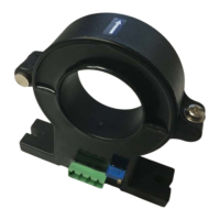
Installation Guidance
To minimize noise that may interfere with the output signal of the probe, the converter box
must be mounted close to the FCCP. It is suggested to mount the converter box in the Panduit
tray or on a fire-retardant mounting board using the provided wings. It is not recommended to
mount the converter in the cabinet.
The screened cable from the probe must have the screen connected to the ground lug on the
converter box.
The Frontier Interface Cable will connect into an unused Current Probe port on the Frontier
system. This port must be programed in the current settings to measure charge current as
opposed to discharge current.
Excess cables should be coiled and dressed or shortened. When shortening cables, play close
attention to the cable terminations and tin cables if necessary.
FCCP Calibration - When setting up an FCCP, it is recommended that the unit is allowed to stabilize
for 25 minutes with no current flowing through the sensor before zeroing the CT in Frontier. The FCCP
interface unit will also need to be zeroed before the FCCP is installed. Follow these steps to calibrate and
zero the probe before finishing installation.
1. If installed over the inter-tier strap or inter-cell cable connection, remove the probe from the
current carrying cable.
2. Ensure the probe is closed and latched. Place the latched closed probe next to the monitored
cable.
3. Disconnect the power to the converter box. Press and hold the two buttons on the front of the
converter box while powering the unit back on, holding until all LEDs on the converter box turn
Red. This will take approximately 10-15 seconds.
4. Once lit, release the buttons and wait until all LEDs go out. This will take approximately 10-15
seconds.
5. Once LEDs have gone out, cycle the power on the converter box one more time.
6. In Frontier, go to the settings menu and select Configure CTs. The CT should be set as a charge
only CT with a range of 5 amps.
7. On the same configuration page, click on ‘Zero CT’.
8. Verify under Reading that the float current is zero.
9. Refit the CT around the cable and verify float current (typically 0.100-0.200 A).
The arrow on a FCCP should be oriented with the flow of current (away from the battery if on the
negative bus and toward the battery of on the positive bus) to display float current as a positive value.