Cellwatch Frontier System Installation & User Manual
Section I – Installation Guide-43
If the number of cells in the string is not divisible by four, ensure each DCM6-L is wired across at least
three cells. Most of the DCM units on the string will monitor four cells with the last one, two, or three
(depending on the remainder) monitoring three cells.
Connecting a DCM
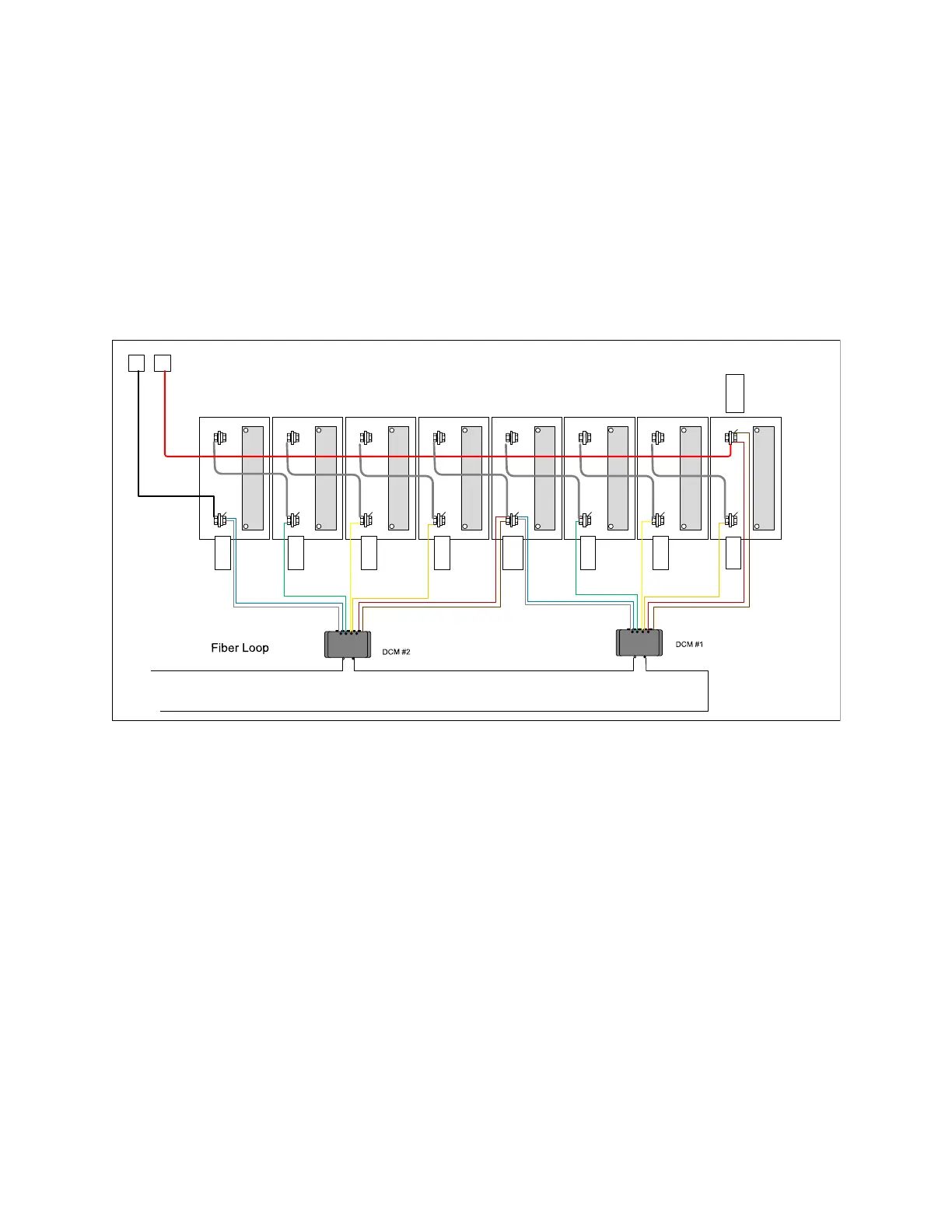
The DCM wire order of connection is not important when powering on the DCM, but placement of the
wires to the cells is very important. Built-in circuit protection allows the DCM to be connected across the
cells in any configuration and not damage the battery. Follow the connection diagram to ensure the
DCM is connected properly; it is replicated here for easy reference:
+ -
+ -
G
Bl, W,
Br, R
+ -
+ -
Br, R
O
Y
+ -
+ -
+ -
+ -
+
-
O
Y
G
Bl, W
DCM
DCM
When powered on, the DCM will emit an audible “beep” and flash the LEDs. Once powered on, the DCM
is active and will remain active drawing current from the battery regardless of the open or closed state
of the battery. The DCM is equipped with a deep sleep mode that will drop the DCM current draw to
below 3 mA after 25 hours of inactivity, allowing the battery to survive a longer duration with a parasitic
load connected.
Do not connect the DCM to the cells such that any potential between any leads exceeds the
operational voltage of the DCM. Connecting the DCM to excessive voltages beyond the
functional range may damage the unit. The DCM is designed to withstand temporary high over-
voltage conditions or reverse wiring conditions but will not withstand excessive voltages long
term.
Always secure the DCM wires by connecting to a tab washer. Do not allow loose DCM wires to
hang in the cabinet. Excess wire should be dressed in a clean manner by zip tying the wires to
themselves in “sticks.” Cables can and should be routed between cells to provide a clean
appearance.