Cellwatch Frontier System Installation & User Manual
Section I – Installation Guide-27
. If needed an offline driver for Windows 7 and Windo
the USB drive provided with the Frontier Unit.
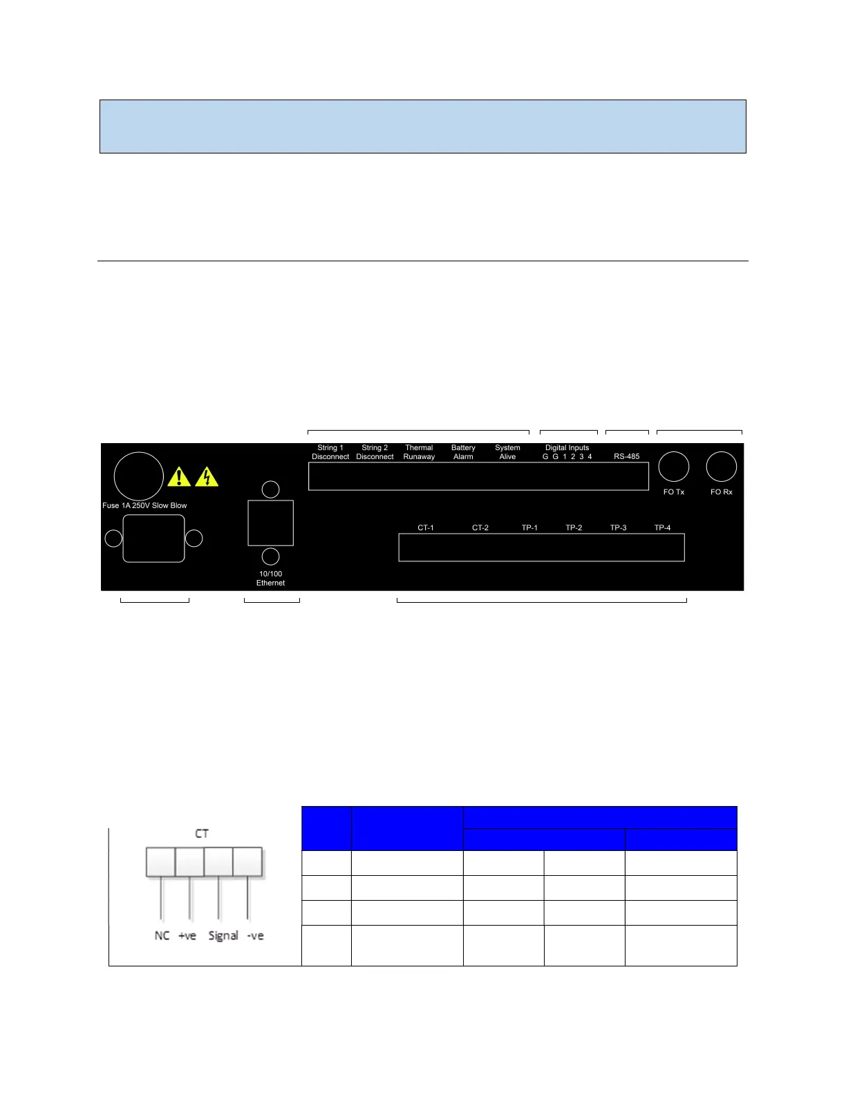
Frontier Back Panel
The back panel of the Frontier system is explained in the following section.
Input Connections
The Frontier unit has various input connections as shown below. This section addresses the pin-out and
wiring recommendations for each connection.
Relay Outputs
Digital
Inputs
RS-485 Fiber Optic
Sensor InputsEthernetPower
The back panel of the Frontier wall mount model. The rack mount Frontier (not pictured) features a similar layout.
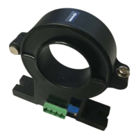
Current Transducer (CT)
Current transducers can be connected to the Frontier system to monitor for discharge and charge
events. Only use current transducers that are approved by NDSL. Below is the wiring diagram for
connecting a CT to the Frontier unit.
Beginning from left to right:
Pin # CT Connector
1 No Connection White White No Connection
2 +Ve Red Red Red
3 Signal Green Yellow Green
4 -Ve
Black +
Screen
Blue +
Screen
Black + Screen