Cellwatch Frontier System Installation & User Manual
Section I – Installation Guide-25
The wall mount model weighs 1.6 lbs. and the mounting arrangement should be capable of supporting
this weight, plus any user installed equipment and cables. If necessary, when mounting to drywall a
backing plate should be used. The installer should use at least a ½” thick plywood sheet (covered with
fire-retardant paint), or a 1/16” steel, or a 1/8” aluminum plate, for mounting. The plate should be at
least 12” x 12” and large enough to be firmly secured by screws that go through the plate and dry wall,
and then directly into at least two or more supporting studs. The wall mount unit should never be
directly mounted to the drywall itself. A Frontier Wall Mount Cabinet Kit is also available.
Note: Strain reliefs should be used to prevent wires from being pulled out of the connectors
unintentionally. This is especially important for the power cable. P-Clips are recommended but not
supplied due to the variations in the installation of the cabling. It is very important that the placement
of a strain relief for the power cable, or even the mounting location of the Frontier system itself, does
not in any way restrict access to, or inhibit the action of disconnecting the power cable from the unit.
The power cable is considered the disconnecting device for the Frontier system.
Exposed Installations
Frontier is designed for internal use only and should not be deployed outside or directly exposed to
harsh weather environments. Installations that have the possibility of exposing the Frontier system
directly to external elements, either through active fans or passively through vents, must be avoided.
The Frontier unit could be protected from external moisture and debris by mounting the Frontier into a
weather-proof enclosure or by deploying environmentally protected hardware.
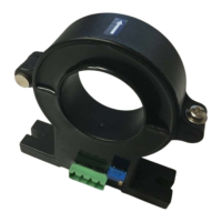
Environmentally protected equipment will have a part number indicating the circuitry is protected. The
part number will end in a –EP. The Frontier unit, Temp Probes, Current Transducers, FED units and FED
adapters are available in EP. Contact NDSL prior to purchasing equipment for exposed installations to
review available options.
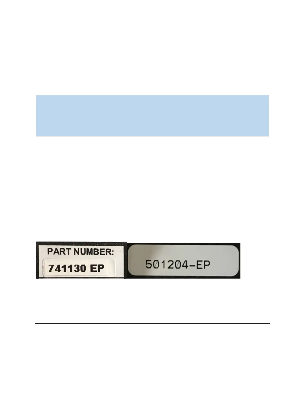
DCM5-DS and FED Adapter part numbers indicating EP
Frontier Front Panel
The front panel of the Frontier wall mount model is shown below. The rack mount Frontier unit features
a similar layout. For an explanation of the various status indicators located on the front of the Frontier
unit, see the table below.