Cellwatch Frontier System Installation & User Manual
Section III – Configuration Build and Hardware Integration Guide-110
20. Assign alarms to the Frontier unit.
Charger Cables
Example Configuration: 1 Battery, (1) 60 jar string measuring charger cables, with DCM 5T, 2
temperature probes, 2 current probes
1. Select Battery Design from the Settings menu.
2. Select Start new configuration.
3. Hardware
a. Wiring Pattern: Cells only.
b. Temperature probes: TP1 and TP2.
c. Current transducers: CT1 and CT2.
d. Leave all digital bits checked unless they need to be disabled.
4. Click Next.
5. Name the Battery and String.
6. Assign TP1 and TP2 to String 1 by clicking the corresponding check boxes.
7. Assign CT1 and CT2 to String 1 by clicking the corresponding check boxes.
8. Assign DIBs as needed.
9. Enter “62” into the Channel count field (60 jars + 2 charger cables).
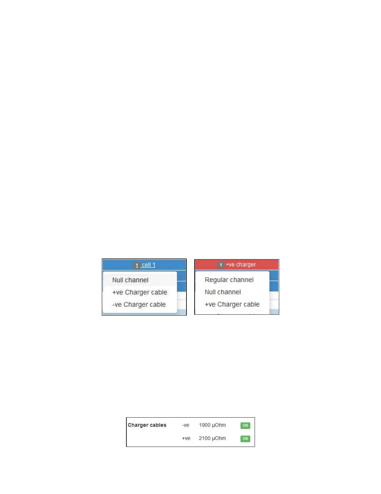
a. Based on the hardware layout, the channels needed for monitoring the charger cables
will need to be left-clicked and changed to a status of “Charger cable.” This will change
the color of the channel to red and reorder the cell labeling.
b. Make note of the number of DCMs needed for this configuration. Ensure the correct
amount of hardware is used.
10. Make no changes to the Electrolyte Level Detectors (no FEDs) and Temperature Compensation
(no).
11. Click Next.
12. Enter in the operator password of ‘deafcat’.
13. Click Save and wait for the “Settings Saved” confirmation.
14. Select Home in the Navigation Bar to see the new readings. The charger cable’s ohmic values
will be included as a separate line item on the Home page.