Cellwatch Frontier System Installation & User Manual
Section III – Configuration Build and Hardware Integration Guide-111
15. Select Configure CTs in the Settings menu, located in the Navigation Bar.
16. Select the Type of CT that is connected to the corresponding ports.
17. Select the Capacity rating of the CT.
18. Zero if needed.
19. Assign alarms to the Frontier unit.
DCM6-R
Example Configuration: 1 Battery, (1) 12 jar string with DCM 6-L and a single DCM 6-R measuring string
voltage and ripple, 1 temperature probe, 1 current probe
1. Select Battery Design from the Settings menu.
2. Select Start new configuration.
3. Hardware
a. Wiring Pattern: Cells and Straps.
b. Temperature probes: TP1 and TP2.
c. Current transducers: CT1 and CT2.
d. Leave all digital bits checked unless they need to be disabled.
4. Click Next.
5. Name the Battery and String.
6. Assign TP1 to String 1 by clicking the corresponding check boxes.
7. Assign CT1 to String 1 by clicking the corresponding check boxes.
8. Assign DIBs as needed.
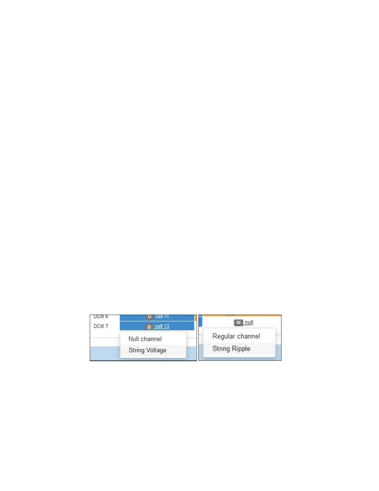
9. Enter “28” into the Channel count field (7 DCM units * 4 channels each).
a. Left click the 4
th
channel on DCM #6 to null the last channel. This channel will not be
measured.
b. Left click the 1
st
channel on DCM #7 and choose ‘String Voltage’. Left click the 2
nd
channel on DCM #7 and choose ‘String Ripple’. This should be the DCM6-R unit used to
measure string voltage and ripple.
c. Make note of the number of DCMs needed for this configuration. Ensure the correct
amount of hardware is used. See snapshot below for example layout.