Cellwatch Frontier System Installation & User Manual
Section I – Installation Guide-55
Strings or sub-strings not divisible by four
DCM units measure four channels of data at a time. If the battery is designed such that the measuring
channels are NOT DIVISIBLE by four then special techniques must be used that require planning. In these
situations, data channels must be nulled and special consideration should be taken into account with
regards to the operational voltage of the DCM. Examples are described below.
58 VLA containing two dry cells
In some configurations, there may be dry cells contained within the battery string to provide the proper
DC voltage for the plant. In these configurations if a DCM is monitoring on the individual cell level, then
two DCM channels will be joined together (i.e. readings will be zeroed and nulled). The Frontier
automatically accounts for these channels based on the voltage and the ohmic value readings.
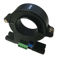
16V VRLA jars
Due to space requirements, sometimes 16V VRLA jars may be used instead of larger 12V or 2V
configurations. The DCM6-H has the ability to connect directly across 4 jars. Always remember to never
connect the DCM in parallel with the DC charger as this will provide less accurate measurements.
Sub-strings of 2-volt wet cells not divisible by four
The DCM5 and DCM6-L are both capable of working on a string powered by three 2V cells. Any
configuration requiring nulled channels on a 2V VLA/VRLA system must null only channel 4. Thus, if
three channels are required to be nulled then three DCM modules will each have one null channel.
Because this is a highly unusual configuration, it is recommended that you contact NDSL to ensure that
the tabbing and DCM wiring is done correctly.
DCM Connection Order
The order in which the wires are initially installed does not matter to the DCM. Two suggested methods
are displayed below, either is acceptable.
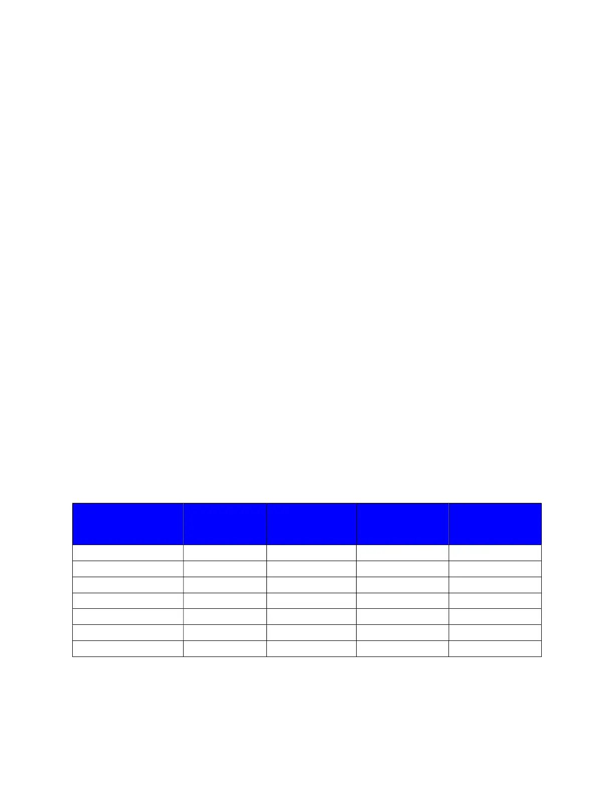
Method 1
Connection order Cable Colors
(2V system)
(12V system)
1st White Most Negative 0 volts 0 volts
2nd Blue Most Negative 0 volts 0 volts
3rd Green 2 volts 12 volts
4th Yellow 4 volts 24 volts
5th Orange 6 volts 36 volts
6th Red Most Positive 8 volts 48 volts
7th Brown Most Positive 8 volts 48 volts