CG Drives & Automation, 01-5326-01r5 Options 227
13.5 Gland kits
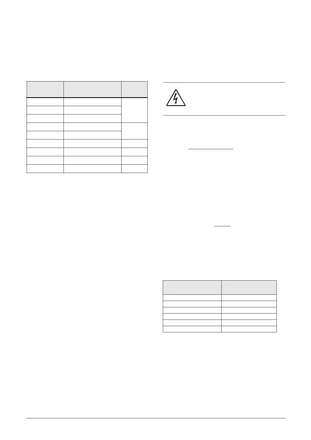
Gland kits are available for frame sizes B, C and D.
Optional gland kits are available for IP54 frame sizes B, C,
D, C69 and D69.
Metal EMC glands are used for motor and brake resistor
cables.
13.6 EmoSoftCom
EmoSoftCom is an optional software that runs on a personal
computer. It can also be used to load parameter settings
from the AC drive to the PC for backup and printing.
Recording can be made in oscilloscope mode. Please contact
CG Drives & Automation sales for further information.
13.7 Brake chopper
All AC drive sizes AC drives with cable inlet on short side
can be fitted with an optional built-in brake chopper. The
brake resistor must be mounted outside the AC drive. The
choice of the resistor depends on the application switch-on
duration and duty-cycle. This option can not be after
mounted.
The following formula can be used to define the power of
the connected brake resistor:
Where:
P
resistor
required power of brake resistor
Brake level V
DC
brake voltage level (see Table 45)
Rmin minimum allowable brake resistor
(see Table 46, Table 47 and Table 48)
ED effective braking period. Defined as:
t
br
Active braking time at nominal braking
power during a 2 minute operation
cycle.
Maximum value of ED = 1, meaning continuous braking.
Part Number Current (dimension)
Frame
size
01-4601-21 3 - 6 A (M16 - M20)
B01-4601-22 8 - 10 A (M16 - M25)
01-4601-23 13 - 18 A (M16 - M32)
01-4399-01 26 - 31 A (M12 - M32)
C
01-4399-00 37 - 46 A (M12 - M40)
01-4833-00 61 - 74 A (M20 - M50) D
01-7248-00 2 - 10 A (M20 - M25) C69
01-7248-10 13 - 25 A (M20 - M32) C69
01-7247-00 33 - 58 A (M20 - M40) D69
WARNING!
The table gives the minimum values of the
brake resistors. Do not use resistors lower
than this value. The AC drive can trip or even
be damaged due to high braking currents.
Table 45
Supply voltage (V
AC
)
(set in menu [21B]
Brake level (V
DC
)
220–240 380
380–415 660
440–480 780
500–525 860
550–600 1000
660–690 1150
P
resistor
=
(Brake level V
DC
)
2
R
min
x ED

 Loading...