218 Troubleshooting, Diagnoses and Maintenance CG Drives & Automation, 01-5326-01r5
*) Refer to table Table 44regarding which Desat or
Power Fault is triggered.
12.2 Trip conditions, causes
and remedial action
The table later on in this section must be seen as a basic aid
to find the cause of a system failure and to how to solve any
problems that arise. An AC drive is mostly just a small part
of a complete AC drive system. Sometimes it is
difficult to determine the cause of the failure, although the
AC drive gives a certain trip message it is not always easy to
find the right cause of the failure. Good knowledge of the
complete drive system is therefore
necessary. Contact your supplier if you have any questions.
The AC drive is designed in such a way that it tries to avoid
trips by limiting torque, overvolt etc.
Failures occurring during commissioning or shortly after
commissioning are most likely to be caused by incorrect
settings or even bad connections.
Failures or problems occurring after a reasonable period of
failure-free operation can be caused by changes in the system
or in its environment (e.g. wear).
Failures that occur regularly for no obvious reasons are
generally caused by Electro Magnetic Interference. Be sure
that the installation fulfils the demands for installation
stipulated in the EMC directives. See chapter, EMC and
standards.
Sometimes the so-called “Trial and error” method is a
quicker way to determine the cause of the failure. This can
be done at any level, from changing settings and functions to
disconnecting single control cables or replacing entire drives.
The Trip Log can be useful for determining whether certain
trips occur at certain moments. The Trip Log also records
the time of the trip in relation to the run time counter.
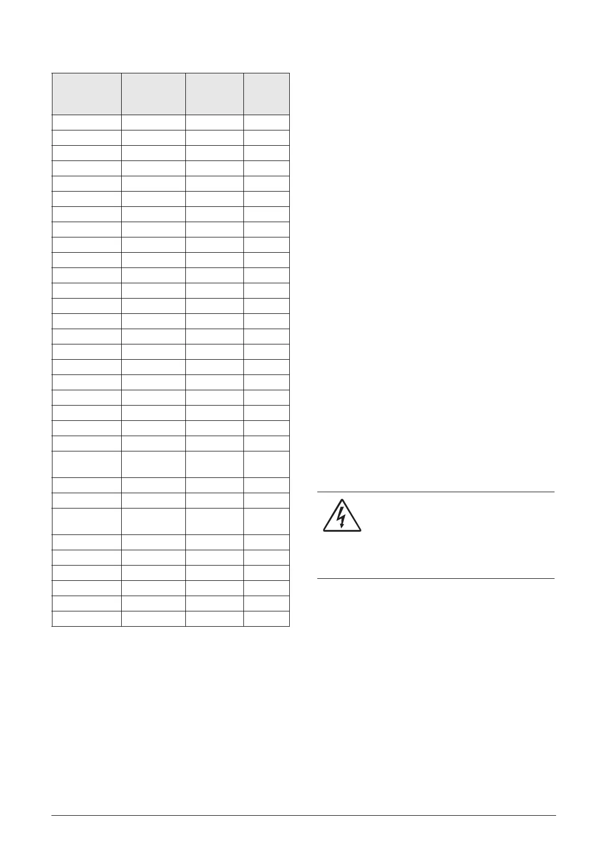
Table 43 List of trips and warnings
Trip/Warning
messages
Selections
Trip
(Normal/
Soft)
Warning
indicators
(Area D)
Motor I
2
t Trip/Off/Limit Normal/Soft I
2
t
PTC Trip/Off Normal/Soft
Motor PTC On Normal
PT100 Trip/Off Normal/Soft
Motor lost Trip/Off Normal
Locked rotor Trip/Off Normal
Ext trip Via DigIn Normal/Soft
Ext Mot Temp Via DigIn Normal/Soft
Mon MaxAlarm Trip/Off/Warn Normal/Soft
Mon MinAlarm Trip/Off/Warn Normal/Soft
Comm error Trip/Off/Warn Normal/Soft
CRIO Dev Via Option Normal
CRIO Comm Via Option Normal
Encoder Trip/Off Normal
Pump Via Option Normal
Over temp On Normal OT
Over curr F On Normal
Over volt D On Normal
Over volt G On Normal
Over volt On Normal
Over speed On Normal
Under voltage On Normal LV
LC Level
Trip/Off/Warn
Via DigIn
Normal/Soft LCL
Desat ### * On Normal
DClink error On Normal
Power Fault
PF #### *
On Normal
Ovolt m cut On Normal
Over voltage Warning VL
Safe stop Warning SST
Brake Trip/Off/Warn Normal
OPTION On Normal
Internal error Normal
WARNING!
If it is necessary to open the AC drive or any
part of the system (motor cable housing,
conduits, electrical panels, cabinets, etc.) to
inspect or take measure-ments as suggested in this
instruction manual, it is absolutely necessary to read
and follow the safety instructions in the manual.

 Loading...