38 Installation CG Drives & Automation, 01-5326-01r5
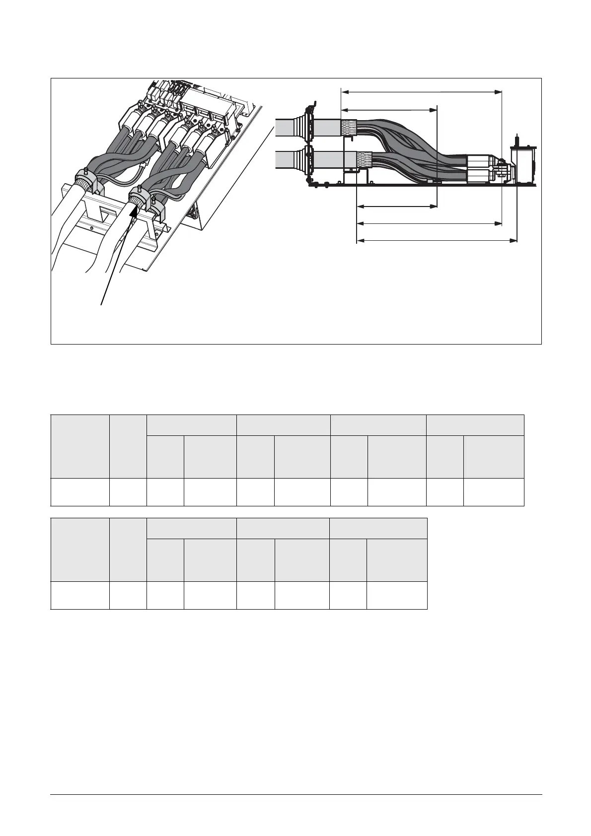
Fig. 55 indicates the distance from the cable clamp to the connection bolts for decision of stripping lengths for the cables.
Fig. 55 Distances from the cable clamp to the connection bolts size FA.
Table 17 Distances from the cable clamp to the connection bolts for mains, motor, brake and earth cables for frame size FA.
* Connect with cable lugs.
3.4.2 Fuse data
Please refer to the chapter Technical data, section 14.6, page 248.
Model VFX
Frame
size
Mains cable 1 Motor cable 1 Brake cable Earth cable
B
mm
(in)
Bolt
dimension
B
mm
(in)
Bolt
dimension
C
mm
(in)
Bolt
dimension
A
mm
(in)
Bolt
dimension
48-365-54 FA
360
(14.2)
M10 bolt*
360
(14.2)
M10 bolt*
400
(15.7)
M8 bolt*
270
(10.6)
M8 bolt*
Model VFX
Frame
size
Mains cable 2 Motor cable 2 Earth cable
D
mm
(in)
Bolt
dimension
D
mm
(in)
Bolt
dimension
E
mm
(in)
Bolt
dimension
48-365-54 FA
400
(15.7)
M10 bolt*
400
(15.7)
M10 bolt*
320
(12.6)
M8 bolt*
Recommended screen length
for Motor and brake cables is approximate 35 mm (1.4 in).

 Loading...