206 CG Drives & Automation, 01-5326-01r5
11.9.2 Status [720]
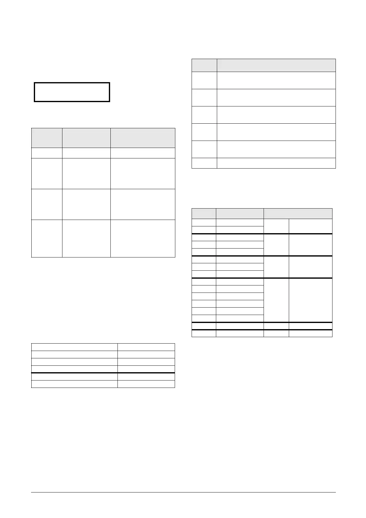
VSD Status [721]
Indicates the overall status of the AC drive.
Fig. 142 AC drive status
Example: “A/Key/Rem/TL”
This means:
A: Parameter Set A is active.
Key: Reference value comes from the keyboard (CP).
Rem: Run/Stop commands come from terminals 1-22.
TL: Torque Limit active.
Communication information
Description of communication format
Integer values and bits used
Example:
Previous example “A/Key/Rem/TL”
is interpreted “0/1/0/4”
In bit format this is presented as
In the example above it is assumed that we have no trip or
warning condition (the alarm LED on the control panel is
off).
Display
position
Function Status value
1 Parameter Set A,B,C,D
222
Source of
reference value
-Rem (remote)
-Key (keyboard)
-Com (Serial comm.)
-Opt (option)
333
Source of Run/
Stop command
-Rem (remote)
-Key (keyboard)
-Com (Serial comm.)
-Opt (option)
44 Limit functions
- - - -No limit active
-VL (Voltage Limit)
-SL (Speed Limit)
-CL (Current Limit)
-TL (Torque Limit)
Modbus Instance no/DeviceNet no: 31015
Profibus slot/index 121/159
EtherCAT and CANopen index (hex) 23f7
Profinet IO index 1015
Fieldbus format UInt
Modbus format UInt
721 VSD Status
Stp 1/222/333/44
Bit Integer representation
1 - 0
Active Parameter set, where
0=A, 1=B, 2=C, 3=D
4 - 2
Source of Reference control value, where
0=Rem, 1=Key, 2=Com, 3=Option
7 - 5
Source of Run/Stop/Reset command, where
0=Rem, 1=Key, 2=Com, 3=Option
13 - 8
Active limit functions, where
0=No limit, 1=VL, 2=SL, 3=CL, 4=TL
14
Inverter is in warning (A warning condition is
active)
15 Inverter is tripped (A Trip condition is active)
Bit Interpretation Integer representation
0 LSB 0
A(0) Parameter set
10
21
Key (1) Source of control30
40
50
Rem (0)
Source of
command
60
70
80
TL (4) Limit functions
90
10 1
11 0
12 0
13 0
14 0 Warning condition
15 MSB 0 Trip condition
 Loading...
