80 Operation via the Control Panel CG Drives & Automation, 01-5326-01r5
Remote mode
When the AC drive is switched to REMOTE operation, the
AC drive will be controlled according to selected control
methods in the menu’s “Reference Control [214]”, “Run/
Stop Control [215]” and “Reset Control [216]”.
To monitor the actual Local or Remote status of the AC
drive control, a “Loc/Rem” signal is available on the
Digital Outputs or Relays. When the AC drive is set to
Local, the signal on the DigOut or Relay will be active/high,
in Remote the signal will be inactive/low. See menu “Digital
Outputs [540]” and “Relays [550]”.
10.2.8 Function keys
The function keys operate the menus and are also used for
programming and read-outs of all the menu settings.
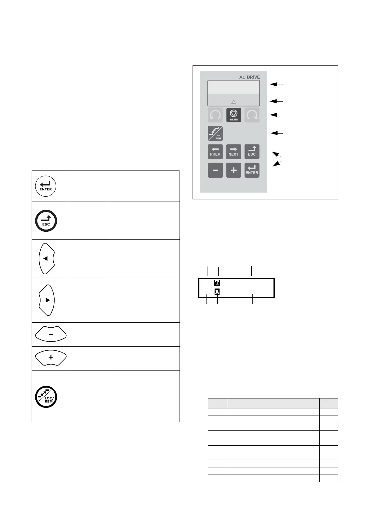
10.3 Control panel with 2-line
display
Fig. 82 Control panel display, LEDs and Keys.
10.3.1 The display
The display is back lit and consists of 2 rows, each with
space for 16 characters. The display is divided into six areas.
The different areas in the display are described below:
Fig. 83 The display
Area A:Shows the actual menu number (3 or 4
digits).
Area BShows if the menu is in the toggle loop or the
AC drive is set for Local operation.
Area C:Shows the heading of the active menu.
Area D *:Shows the status of the AC drive (3 digits).
The following status indications are possible:
Ta b l e 2 9 Fu n c t i o n k e y s
ENTER key:
-step to a lower menu
level
- confirm a changed
setting
ESCAPE key:
- step to a higher
menu level
- ignore a changed
setting, without
confirming
PREVIOUS
key:
- step to a previous
menu within the same
level
- go to more significant
digit in edit mode
NEXT key:
-step to a next menu
within the same level
- go to less significant
digit in edit mode
- key:
- decrease a value
- change a selection
+ key:
- increase a value
- change a selection
TOGGLE and
LOC/REM
key:
- Toggle between menus
in the toggle loop
- Switching between
local
and remote control
- Change the sign of a
value
Digits Description Bit*
Stp Motor is stopped 0
Run Motor runs 1
Acc Acceleration 2
Dec Deceleration 3
Trp Tripped 4
SST
Operating Safe Stop, is flashing when
activated
5
VL Operating at voltage limit 6
SL Operating at speed limit 7
CL Operating at current limit 8
LCD display
LEDs
Control Keys
Toggle Key
Function Keys
221 Motor Volt
Stp M1: 400V

 Loading...