CG Drives & Automation, 01-5326-01r5 Options 231
13.14 Safe Stop option
To realize a Safe Stop configuration in accordance with Safe
Torque Off (STO) EN-IEC 62061:2005 SIL 3 & EN-ISO
13849-1:2006, the following three parts need to be attended
to:
1. Inhibit trigger signals with safety relay K1 (via Safe Stop
option board).
2. Enable input and control of AC drive (via normal I/O
control signals of AC drive).
3. Power conductor stage (checking status and feedback of
driver circuits and IGBT’s).
To enable the AC drive to operate and run the motor, the
following signals should be active:
• "Inhibit" input, terminals 1 (DC+) and 2 (DC-) on the
Safe Stop option board should be made active by con-
necting 24 V
DC
to secure the supply voltage for the
driver circuits of the power conductors via safety relay
K1. See also Fig. 161.
• High signal on the digital input, e.g. terminal 10 in Fig. ,
which is set to "Enable". For setting the digital input
please refer to “11.7.2 Digital Inputs [520]” on
page 172.
These two signals need to be combined and used to enable
the output of the AC drive and make it possible to activate a
Safe Stop condition.
When the "Safe Stop" condition is achieved by using these
two different methods, which are independently controlled,
this safety circuit ensures that the motor will not start
running because:
• The 24VDC signal is disconnected from the "Inhibit"
input, terminals 1 and 2, the safety relay K1 is switched
off.
The supply voltage to the driver circuits of the power
conductors is switched off. This will inhibit the trigger
pulses to the power conductors.
• The trigger pulses from the control board are shut down.
The Enable signal is monitored by the controller circuit
which will forward the information to the PWM part on
the Control board.
To make sure that the safety relay K1 has been switched off,
this should be guarded externally to ensure that this relay did
not refuse to act. The Safe Stop option board offers a
feedback signal for this via a second forced switched safety
relay K2 which is switched on when a detection circuit has
confirmed that the supply voltage to the driver circuits is
shut down. See Table 49 for the contacts connections.
To monitor the "Enable" function, the selection "RUN" on
a digital output can be used. For setting a digital output, e.g.
terminal 20 in the example Table , please refer to “11.7.4
Digital Outputs [540]” on page 178.
When the "Inhibit" input is de-activated, the AC drive
display will show a flashing "SST" indication in section D
(bottom left corner) and the red Trip LED on the Control
panel will be flashing.
To resume normal operation, the following steps have to be
taken:
• Release "Inhibit" input; 24V
DC
(High) to terminal 1
and 2.
• Give a STOP signal to the AC drive, according to the set
Run/Stop Control in menu [215].
• Give a new Run command, according to the set Run/
Stop Control in menu [215].
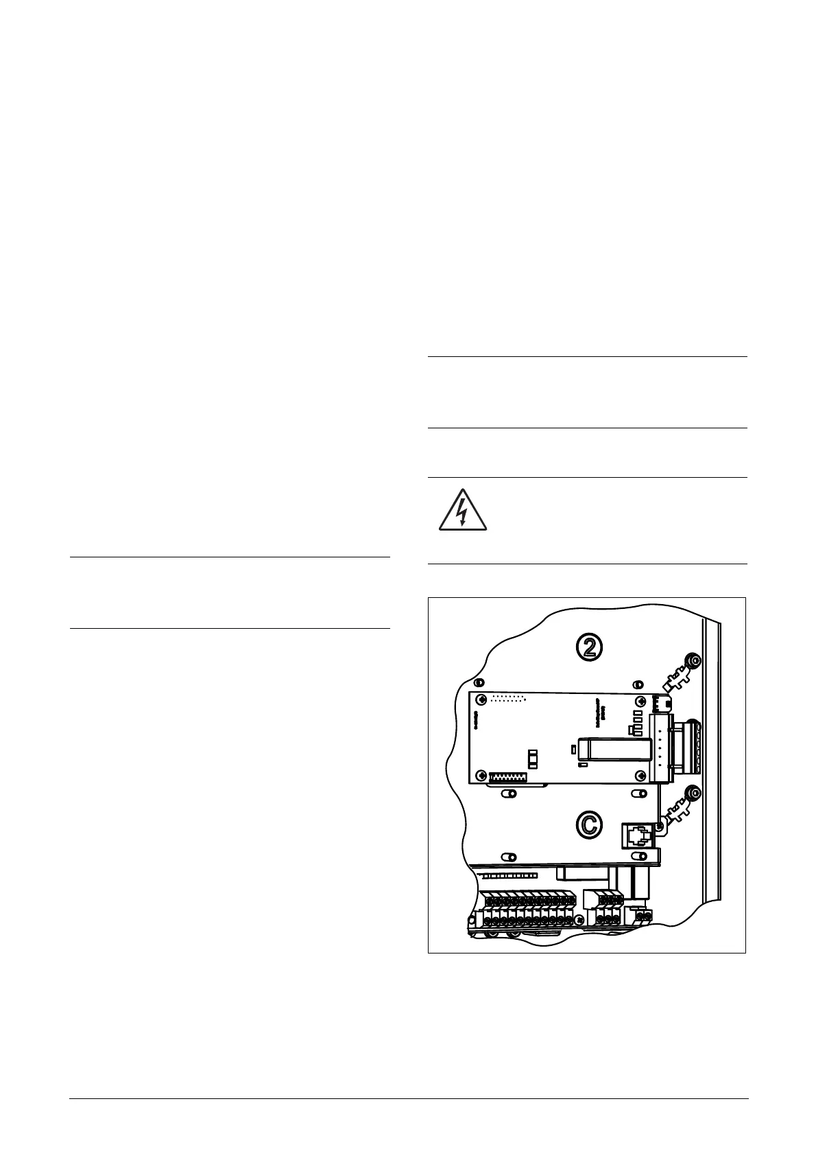
Fig. 159 Connection of safe stop option in size B - D.
NOTE: The "Safe Stop" condition according to EN-IEC
62061:2005 SIL 3 & EN-ISO 13849-1:2006, can only be
realized by de-activating both the "Inhibit" and "Enable"
inputs.
NOTE: The method of generating a STOP command is
dependent on the selections made in Start Signal Level/
Edge [21A] and the use of a separate Stop input via
digital input.
WARNING!
The safe stop function can never be used for
electrical maintenance. For electrical
maintenance the AC drive should always be
disconnected from the supply voltage.

 Loading...