174 CG Drives & Automation, 01-5326-01r5
Additional digital inputs [529] to
[52H]
Additional digital inputs with I/O option board installed,
“B1 DigIn 1 [529]” - “B3 DigIn 3 [52H]”. B stands for
board and 1 to 3 is the number of the board which is related
to the position of the I/O option board on the option
mounting plate. The functions and selections are the same as
“DigIn 1 [521]”.
Communication information
11.7.3 Analogue Outputs [530]
Submenu with all settings for the analogue outputs.
Selections can be made from application and AC drive
values, in order to visualize actual status. Analogue outputs
can also be used as a mirror of the analogue input. Such a
signal can be used as:
• a reference signal for the next AC drive in a Master/Slave
configuration (see Fig. 131).
• a feedback acknowledgement of the received analogue
reference value.
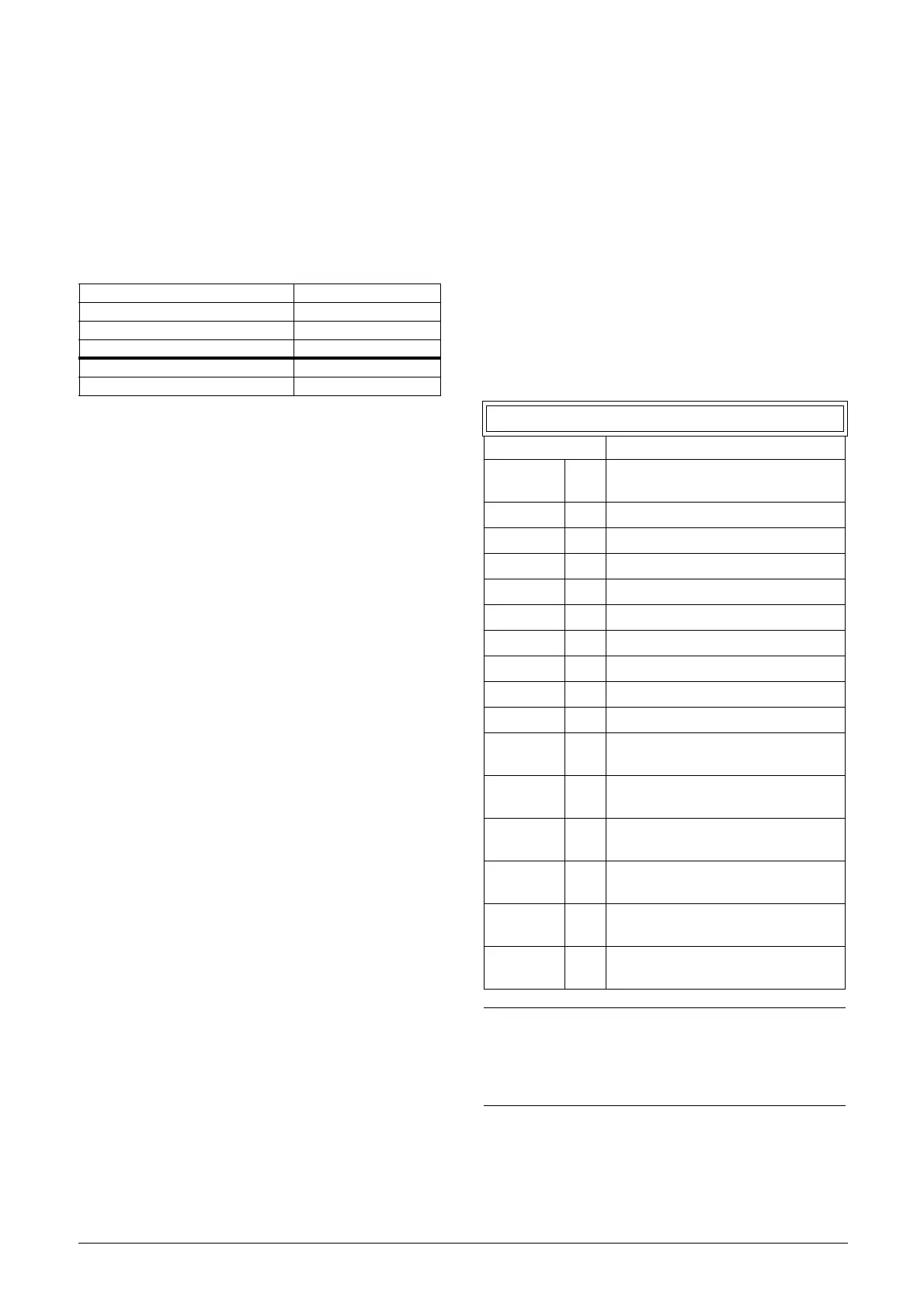
AnOut1 Function [531]
Sets the function for the Analogue Output 1. Scale and
range are defined by AnOut1 Advanced settings [533].
Modbus Instance no/DeviceNet no: 43501–43509
Profibus slot/index 170/150–170/158
EtherCAT and CANopen index (hex) 4dad - 4db5
Profinet IO index 19885 - 19893
Fieldbus format UInt
Modbus format UInt
531 AnOut1 Fc
Default: Speed
Process Val 0
Actual process value according to
Process feedback signal.
Speed 1 Actual speed.
Torque 2 Actual torque.
Process Ref 3 Actual process reference value.
Shaft Power 4 Actual shaft power.
Frequency 5 Actual frequency.
Current 6 Actual current.
El power 7 Actual electrical power.
Output volt 8 Actual output voltage.
DC-voltage 9 Actual DC link voltage.
AnIn1 10
Mirror of received signal value on
AnIn1.
AnIn2 11
Mirror of received signal value on
AnIn2.
AnIn3 12
Mirror of received signal value on
AnIn3.
AnIn4 13
Mirror of received signal value on
AnIn4.
Speed Ref 14
Actual internal speed reference Value
after ramp and V/Hz.
Torque Ref 15
Actual torque reference value
(=0 in V/Hz mode)
NOTE: When selections AnIn1, AnIn2 …. AnIn4 is
selected, the setup of the AnOut (menu [532] or [535])
has to be set to 0-10V or 0-20mA. When the AnOut
Setup is set to e.g. 4-20mA, the mirroring is not
working correct.

 Loading...