CS35 2013.04
3.1.13-183 3.1.13-183Electronic Control System - ME7
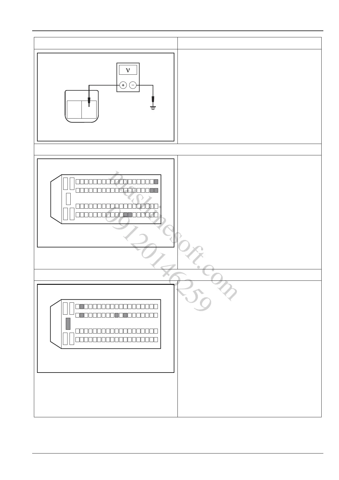
6. Inspect the ECM power supply circuit
A. Turn the ignition switch to position "LOCK".
B. Measure from the back of ECM wiring harness
connector E01.
C. Turn the ignition switch to "ON" position and use a
multimeter to measure the voltage between the
terminals 12, 13, 44, 45 and 63 of the ECM wiring
harness connector E01 and the power supply.
Standard Voltage Value: 11 ~ 14 V
Is the voltage normal?
Y
Go to step 7.
N
Repair and inspect the ECM power supply circuit.
7. Inspect the ECM ground circuit
A. Turn the ignition switch to position "LOCK".
B. Measure from the back of ECM wiring harness
connector E01.
C. Measure the resistance between the ECM wiring
harness connector E01 terminal 3, 51, 53, 61 and
80 and the reliable grounding with a multimeter.
Standard Resistance Value: less than 5 Ω
Is the resistance value normal?
Y
Replace the engine control module.
Refer to: Engine Control Module (3.1.13
Electronic Control System - ME7, Removal
and Installation).
N
Inspect and repair the ECM ground circuit.
Test Conditions Details/Results/Actions
12
3
45
624
2543
4462
63
13
12
45
81
E01
A3113031
12
3
45
6
51
53
61
80
24
2543
4462
6381
E01
A3113032
mashinesoft.com
09120146259