3.1.13-210
CS35 2013.04
3.1.13-210Electronic Control System - ME7
Test Conditions Details/Results/Actions
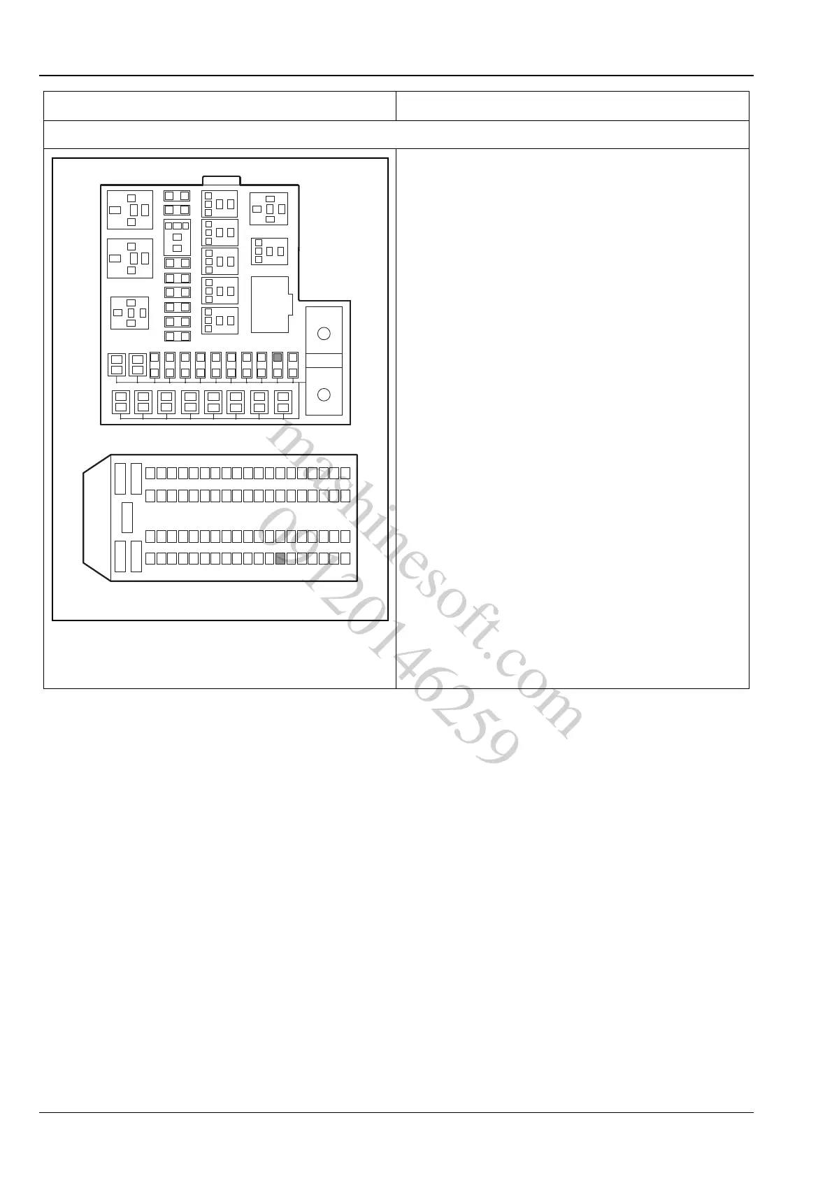
3. Inspect the ECM power supply circuit
A. Turn the ignition switch to position "LOCK".
B. Disconnect the battery negative cable.
C. Remove the fuse EF10 of the engine compartment
fuse and relay box connector C01.
D. Measure the resistance value between terminal 19
of the eengine compartment fuse and relay box C01
and terminal 12 of ECM wiring harness connector
E01.
Standard Resistance Value: less than 5 Ω
E. Remove the fuse IF05.
F. Measure the resistance value between terminal 13
of I/P fuse and relay box P01 fuse IF06 and terminal
13 of ECM wiring harness connector E01.
Standard Resistance Value: less than 5 Ω
G. Remove the fuse EF23.
H. Measure the resistance value between terminal 45
of the engine compartment fuse and relay box C01
fuse EF23 and terminal 44, 45 and 63 of ECM
wiring harness connector E01.
Standard Resistance Value: less than 5 Ω
Is the circuit normal?
Y
Go to step 4.
N
Repair the fault circuit and replace the engine com-
partment electric center if necessary.
E01
C01
2
5
3
1
2
1
4
3
6
5
8
7
10
9
12
11
14
13
16
15
17
18
19
20
21
22
23
24
25
26
27
28
29
30
31
32
33
34
35
36
38
37
40
39
58
57
5
2
1
30
87a
87
85
86
35
2
1
30
87a
87
85
86
35
2
1
35
2
1
86
85
30
87
86
85
30
87
87
86
85
30
87
86
85
30
ER03 ER09
ER08
ER07
ER06
ER04
ER05
ER02
ER01
4142
4344
4546
4748
4950
5152
5354
5556
3
12
3
45
624
2543
4462
63
12
81
A3113104
mashinesoft.com
09120146259