CS35 2013.04
3.1.13-215 3.1.13-215Electronic Control System - ME7
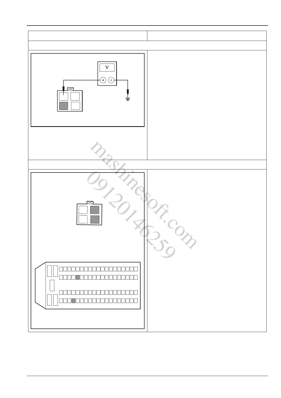
3. Inspect the brake lamp switch power supply voltage
A. Turn the ignition switch to position "LOCK".
B. Disconnect the brake lamp switch wiring harness
connector C14.
C. Turn the ignition switch to position "ON".
D. Measure the voltage between terminals 1 & 3 of
wiring harness connector C14 with reliable
grounding.
Standard Voltage Value: 11 ~ 14 V
E. Connect the brake lamp switch wiring harness
connector C14.
Is the voltage normal?
Y
Go to step 4.
N
Repair the faulty circuit.
4. Inspect the brake lamp switch signal circuit
A. Turn the ignition switch to position "LOCK".
B. Disconnect the battery negative cable.
C. Disconnect the brake lamp switch wiring harness
connector C14.
D. Disconnect the engine control module wiring
harness connector E01.
E. Measure the circuit between terminal 2 of C14 and
terminal 21 of E01 for open circuit, short to ground
or short to power supply.
F. Measure the circuit between terminal 4 of C14 and
terminal 58 of E01 for open circuit, short to ground
or short to power supply.
Is the circuit normal?
Y
Go to step 5.
N
Repair the faulty circuit.
Test Conditions Details/Results/Actions
E01
12
34
C14
12
3
45
624
2543
4462
63
58
21
81
A3113108
mashinesoft.com
09120146259