3.1.13-216
CS35 2013.04
3.1.13-216Electronic Control System - ME7
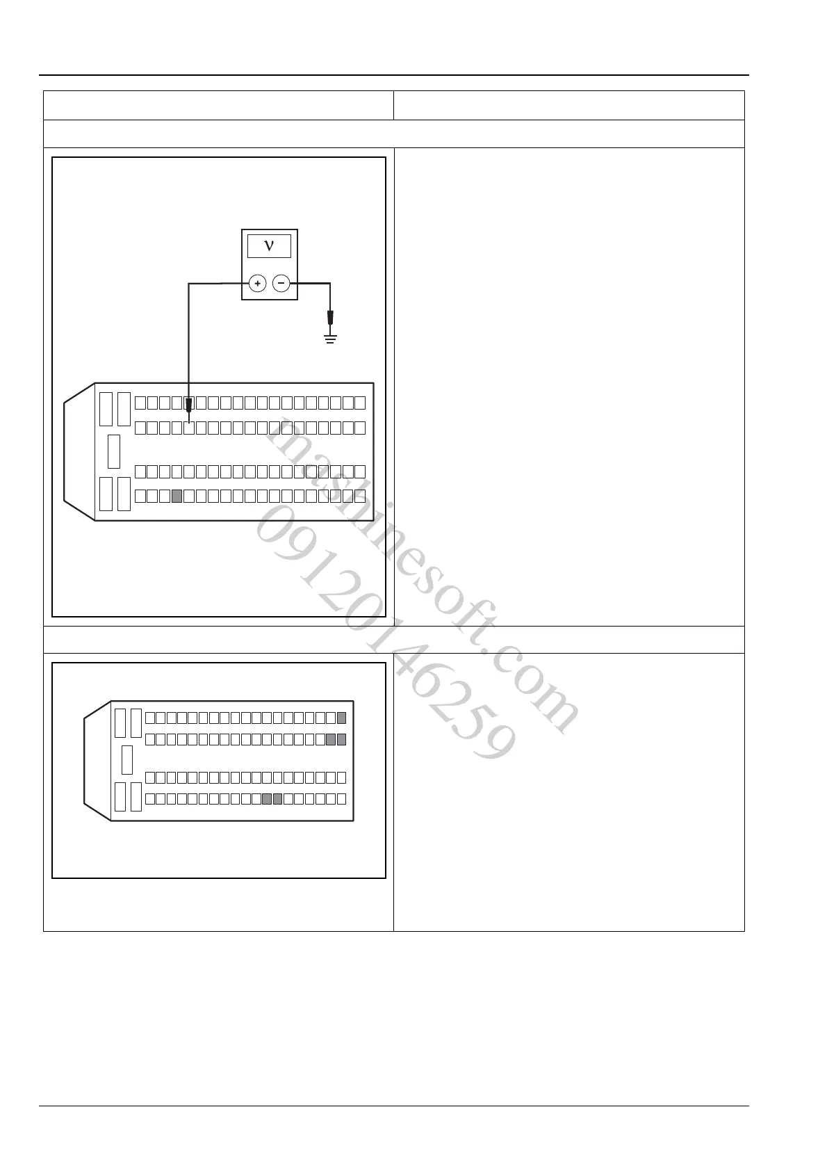
5. Inspect the brake lamp switch
A. Turn the ignition switch to position "LOCK".
B. Disconnect the engine control module wiring
harness connector E01.
C. Turn the ignition switch to "ON".
D. Meanwhile measure the voltage between terminals
21 and 58 of engine control module wiring harness
connector E01 and reliable grounding with a
multimeter.
Standard Voltage:
With brake not applied, voltage at terminal 58:
11 ~ 14 V
voltage at terminal 21: 0 V
With brake applied, voltage at terminal 21: 11 ~
14 V
voltage at terminal 58: 0 V
And the voltage to ground of both terminals are con-
verted at the same time.
Are both circuit voltage and its conversion normal?
Y
Go to step 6.
N
Replace the brake lamp switch.
6. Inspect the ECM power supply circuit
A. Turn the ignition switch to position "LOCK".
B. Measure from the back of ECM wiring harness
connector E01.
C. Turn the ignition switch to "ON" position and use a
multimeter to measure the voltage between the
terminals 12, 13, 44, 45 and 63 of the ECM wiring
harness connector E01 and the power supply.
Standard Voltage Value: 11 ~ 14 V
Is the voltage normal?
Y
Go to step 7.
N
Repair and inspect the ECM power supply circuit.
Test Conditions Details/Results/Actions
E01
12
3
45
624
25
21
43
4462
63
58
81
A3113109
12
3
45
624
2543
4462
63
13
12
45
81
E01
A3113031
mashinesoft.com
09120146259