3.1.13-240
CS35 2013.04
3.1.13-240Electronic Control System - ME7
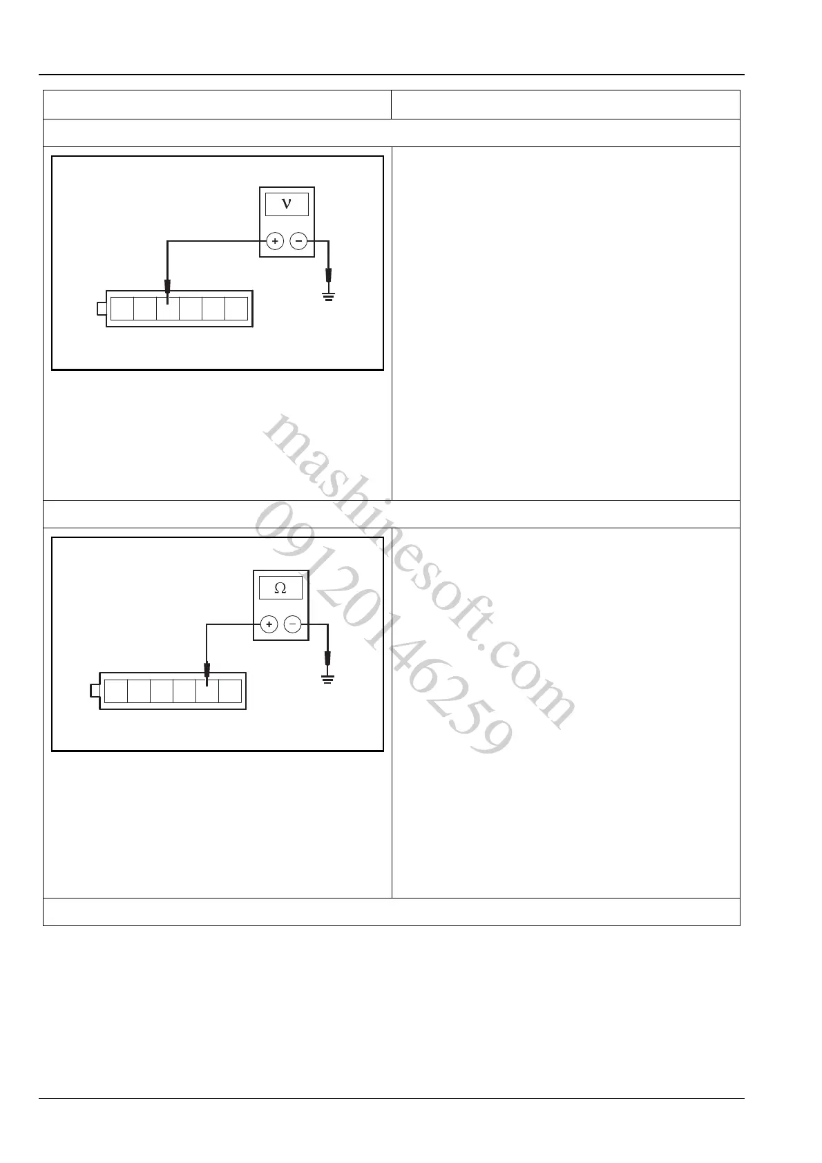
2. Inspect the electronic accelerator pedal position sensor 1 power supply circuit
A. Turn the ignition switch to position "LOCK".
B. Disconnect electronic accelerator pedal position
sensor wiring harness connector C16.
C. Turn the ignition switch to position "ON".
D. Measure the voltage between the terminal 3 of
electronic accelerator pedal position sensor wiring
harness connector C16 and reliable grounding.
Standard Voltage Value: 4.5 ~ 5.5 V
E. Connect the electronic accelerator pedal position
sensor wiring harness connector C16.
Is the voltage normal?
Y
Go to step 3.
N
Repair the fault circuit between terminal 3 of elec-
tronic accelerator pedal position sensor wiring har-
ness connector C16 and terminal 33 of ECM E01.
3. Inspect the electronic accelerator pedal position sensor 1 ground circuit
A. Turn the ignition switch to position "LOCK".
B. Disconnect the electronic accelerator pedal position
sensor wiring harness connector C16.
C. Turn the ignition switch to position "ON".
D. Measure the resistance between the terminal 5 of
electronic accelerator pedal position sensor wiring
harness connector C16 and reliable grounding.
Standard Resistance Value: less than 5 Ω
E. Connect the electronic accelerator pedal position
sensor wiring harness connector C16.
Is the resistance value normal?
Y
Go to step 4.
N
Repair the fault circuit between terminal 5 of elec-
tronic accelerator pedal position sensor wiring har-
ness connector C16 and terminal 36 of ECM wiring
harness connector E01.
4. Inspect the electronic accelerator pedal position sensor 1 signal circuit
Test Conditions Details/Results/Actions
mashinesoft.com
09120146259