CS35 2013.04
3.1.13-241 3.1.13-241Electronic Control System - ME7
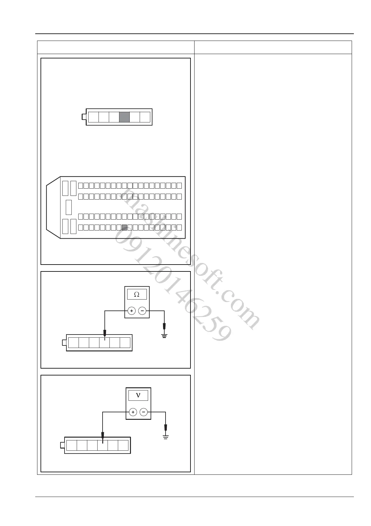
A. Turn the ignition switch to position "LOCK".
B. Disconnect the battery negative cable.
C. Disconnect the electronic accelerator pedal position
sensor wiring harness connector C16.
D. Disconnect the engine control module wiring
harness connector E01.
E. Measure the resistance value between terminal 4 of
electronic accelerator pedal position sensor wiring
harness connector C16 and terminal 16 of ECM
wiring harness connector E01, and check for open
circuit.
Standard Resistance Value: less than 5 Ω
F. Measure the resistance value between the terminal
4 of electronic accelerator pedal position sensor
wiring harness connector C16 and the reliable
grounding. Inspect for short circuit to ground.
Standard Resistance Value: 10 MΩ or more
G. Measure the voltage between the terminal 4 of
electronic accelerator pedal position sensor wiring
harness connector C16 and the reliable grounding.
Inspect for short circuit to power supply.
Standard Voltage Value: 0 V
H. Connect the wiring harness connectors C16 and
E01.
Is the circuit normal?
Y
Go to step 5.
N
Repair the fault circuit between terminal 4 of elec-
tronic accelerator pedal position sensor wiring har-
ness connector C16 and terminal 16 of ECM wiring
harness connector E01.
Test Conditions Details/Results/Actions
E01
146
C16
12
3
45
624
2543
16
4462
6381
A3113124
mashinesoft.com
09120146259