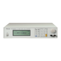
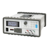
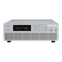
Programmable DC Power Supply 62000P Series Operating & Programming Manual
(3) Analog monitors (V/I Monitor) the output signal. This allows signals to be easily
monitored by external instruments (DMM, Osciliscope, etc). Analog monitoring points
are buffered for protection.
(4) Output indication (DC ON) signal.
(5) Protection state indication (OVP/OCP/OPP/OTP/FAN LOCK/AC FAULT, etc).
(6) CV/CC status indicators.
(7) 8-bit TTL output signal.
(8) Output status indicators.
1.2.4 Input Control Signals
(1) Remote sense input for voltage drop compensation.
(2) Analog reference voltage (APG) input, 0-10VDC or 0-5VDC, for voltage and current.
(3) Remote inhibit control signal (TTL)
1.2.5 Measuring & Editing
(1) Measurement for voltage, current and power.
(2) 10 programs and 100 sequences to edit voltage/current waveform output.
1.3 Specifications
The operating specifications of 62000P Series DC Power Supply are listed below. Besides
the specifications specified particularly, all specifications are tested following the standard
test procedure of Chroma (test condition: 25 ± 5°C and under resistance load).
1-2

 Loading...


