Theory of Operation
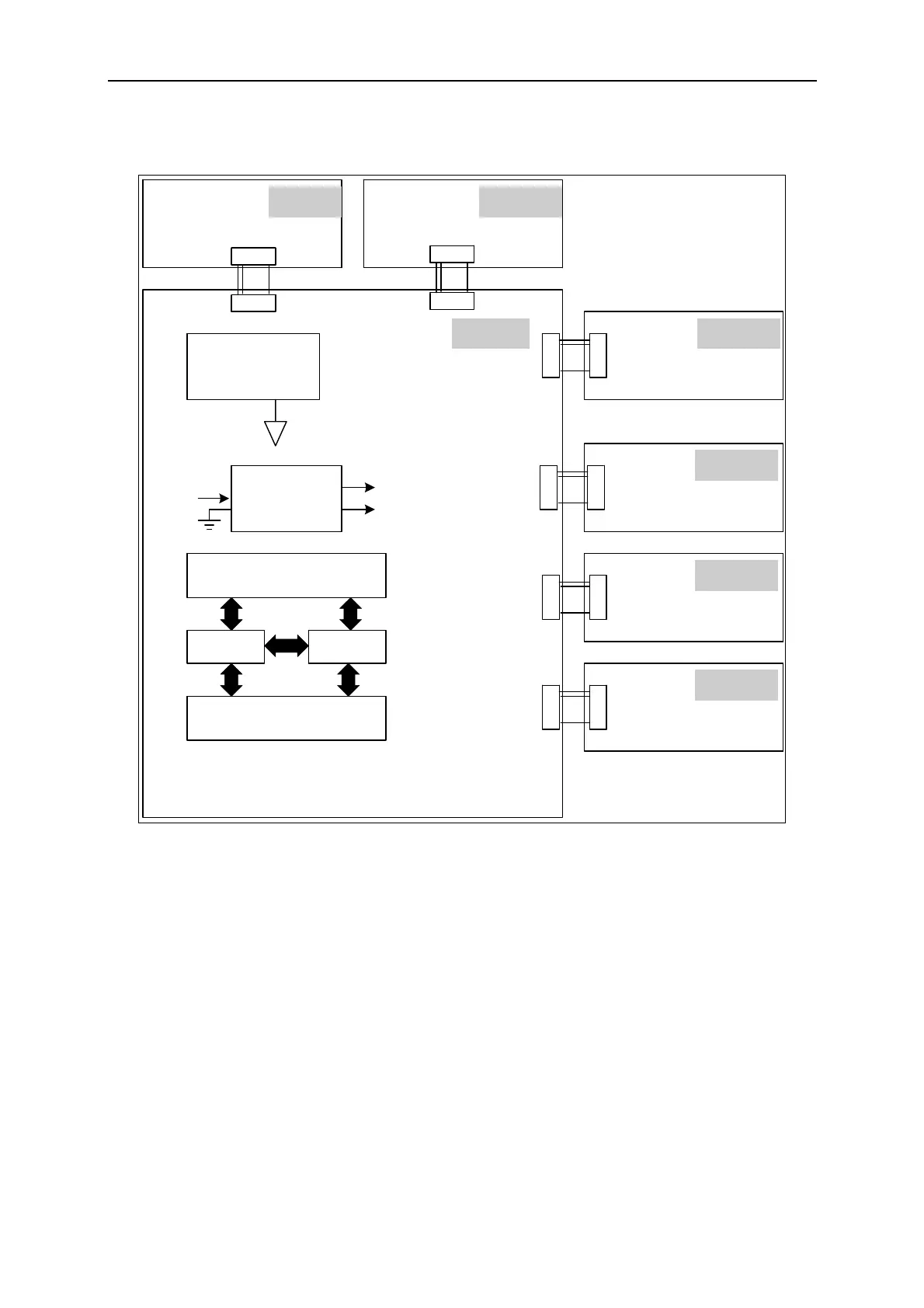
Figure 6-4 shows the digital stage structure.
Isolated APG
APIGND
Linear
Regulator
+5VD
+2.5VD
+3.3VD
Memory
CPLD FPGA
Microprocessor
DGND
RS232,RS485
APG,TTL Signal
GPIB
KEY Pannel
LCD Control
AC/DC(PFC)
DC/DC(BUCK)
C Board
I Board G Board
K Board
D Board
A Board
B Board
Figure 6-4
6.2 Function Description
6.2.1 I/P (PFC) Stage
1. The input stage is a bridge rectifier plus a boost converter with PFC function. The
PWM IC is the UCC3854 of Unitrode and controlled by average current mode under the
switch frequency of 25KHz.
2. The way input stage inhibits inrush current is to switch the relay to a series of 300~400
Ω
resistance during power-on to charge the PFC output capacitance. Turn on another
relay after eight seconds and bypass this 300~400
Ω resistances then enable UCC3854.
3. The PFC output has over voltage protection. When the output voltage is to high, it will
disable UCC3854 and send signal back to CPU to shutdown the system.
6-3

 Loading...
