Programmable DC Power Supply 62000P Series Operating & Programming Manual
3.3.2.5 TTL Option
When the DC Power Supply is outputting, its SYSTEM STATUS connector on the rear panel
offers 8 BIT digital signals for other purpose use. The TTL VALUE range is from
0 to 255, in
addition the system will convert it by binary automatically for easy identification.
1. Use “
”, “
” keys to move the cursor to the column to be set.
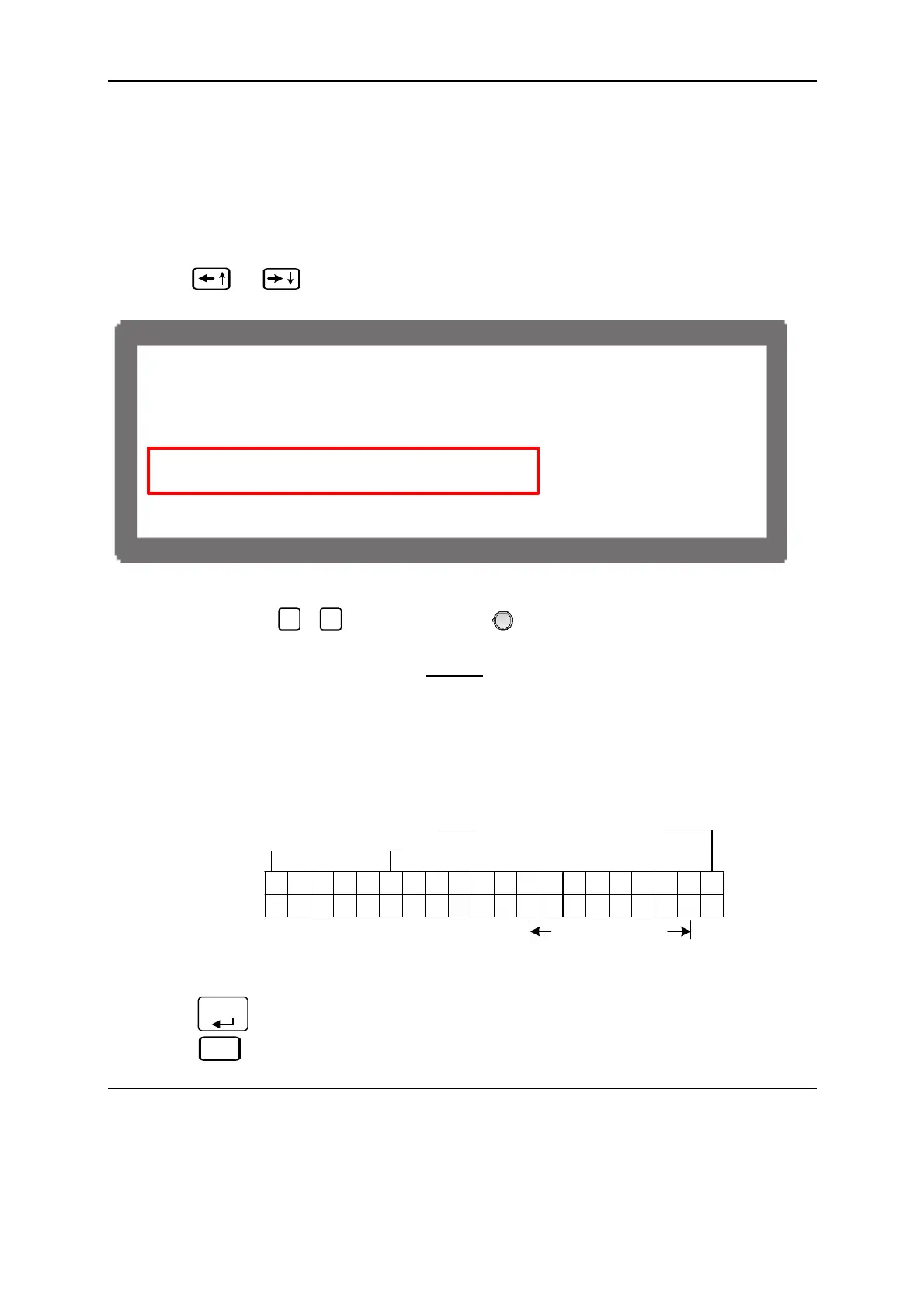
[ O U T P U T S E T U P ]
V L I M I T : M A X = 8 0 . 0 0 V M I N = 0 0 0 . 0 0 V
I L I M I T : M A X = 1 5 . 0 0 A M I N = 0 0 0 . 0 0 A
V S L E
RA T E = 1 . 00 ( V / mS )
I S L E
RA T E = 1 . 00 ( A / mS )
T T L V A L U E = 0 ( D E C )
< B I N A R Y = 0 0 0 0 0 0 0 0 >
Figure 3-24
2. Use the numeric (
0
~
9
) keys or “Rotary” (
) knob to set the value.
The setting range of TTL VALUE is
0 ~ 255, in addition the system will convert it to
binary automatically for easy identification.
Figure 3-25 shows the SYSTEM STATUS pin no. on rear panel, where TTL0~TTL7 is
located at PIN12 ~PIN19, and PIN20 is the signal reference point of PIN8~PIN19
(GND).
1 2 3 4 5 6 7 8 9 10 11 12 13 14 15 16 17 18 19 20
ANALOG PROGRAM
INTERFACE
SYSTEM STATUS
TTL0 ~ TTL7
Figure 3-25
3. Press “
ENTER
” to confirm.
4. Press “
EXIT
” to return to MAIN PAGE.
NOTICE
1. The TTL signal can be set PROGRAM.
2. Table 3-1 shows the TTL pin definition of SYSTEM STATUS.
3-16

 Loading...

