Programmable DC Power Supply 62000P Series Operating & Programming Manual
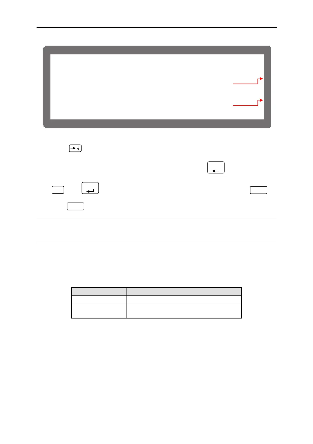
[APG VOLT
GE CAL I B
T I O N ]
C H E C
P G C O N N E C T I O N A N D P
ESS [ E N T E
]
( M E A S . ) O U P U T V O L T A G E F O R M E A S U
E = 0 . 5 V
A C T U A L A P G O U P U T
O L T A G E = 0 . 6 6 V
( M E A S . ) O U P U T V O L T A G E F O R M E A S U
E = 8 . 0 V
A C T U A L A P G O U P U T
O L T A G E = 7 . 6 6 V
]3[
]4[
Figure 3-99
(7) Press “
” again the system will set the output voltage of Pin 5 on the rear panel to
8.0V. The cursor stops at position [4] as Figure 3-99 shows. Input the voltage (2 digits
after decimal point) read by DVM 2 to position [4] and press “
ENTER
” to confirm.
(8) The APG Voltage calibration is done once the above actions are completed. Press
“
SAV E
” and “
ENTER
”to save the calibrated data as Figure 3-95 shows, or press “
EXIT
”
to return to Calibration page without saving.
(9) Press “
EXIT
” to return to MAIN PAGE.
NOTICE
The calibration point may be different for other models (non 62012P-80-60), please operate it
following the instructions displayed.
3.3.7.5 APG Current Calibration
3.3.7.5.1 Hardware Requirements
Device Suggest Model or Capacity
DVM HP 34401A or equivalent DVM
DC Power Supply Any DC Power Supply or DC signal source
that can output 10Vdc and drive 100mA.
Table 3-12
3-60

 Loading...

