Manual Operation
NOTICE
1. When entering into the CALILBRATION page, be sure to check the interface connection
on the rear panel is correct and then press “
ENTER
” to start calibration.
2. If Agilent 34401 is used, the DVM1 and DVM2 can be connected to the front and rear
measurement input terminal respectively.
(3) When in the APG Voltage Calibration pages and the connection is correct, press
“
ENTER
” to confirm.
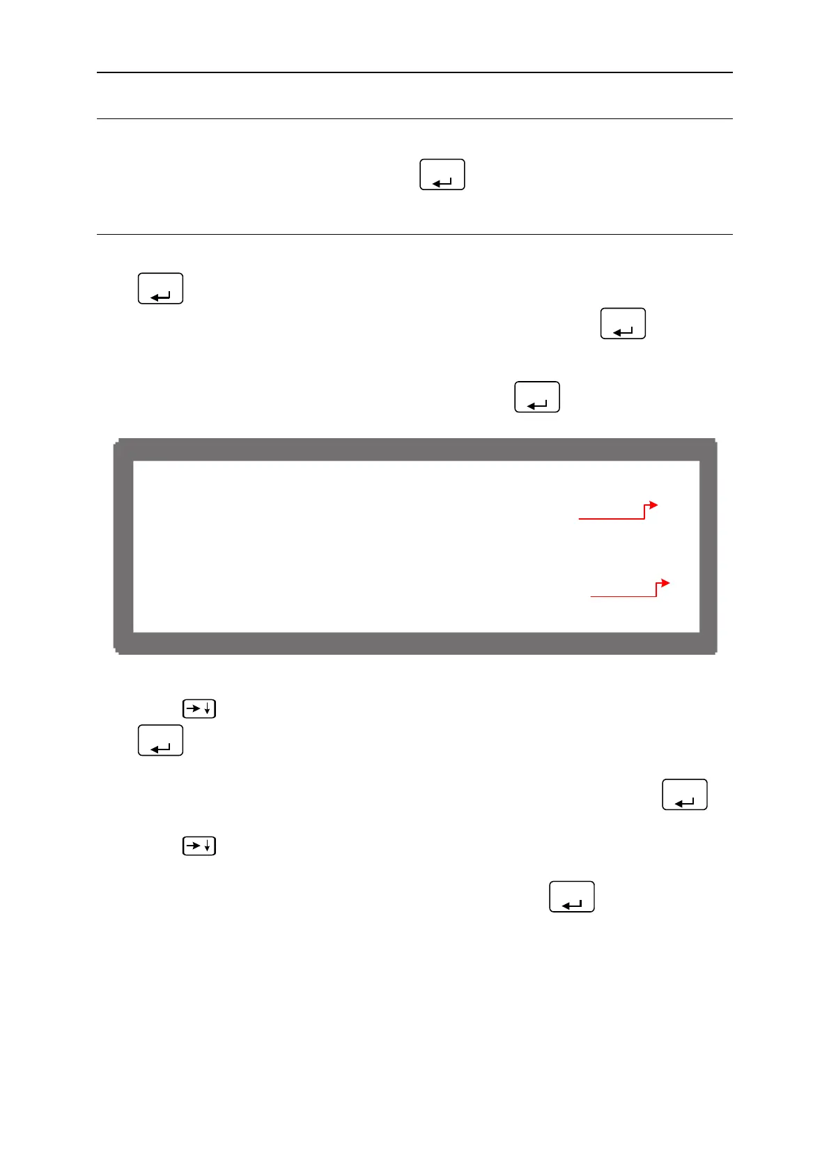
(4) It will ask users to input about 0.5V voltage signal (Pin 3), and press “
ENTER
” the cursor
will stop at position [1] as Figure 3-98 shows. Adjust the Power Supply to 0.5V±0.2V
and use DVM1 to measure the reading of Power Supply. Input the voltage (2 digits after
decimal point) read by DVM 1 to position [1] and press “
ENTER
” to confirm.
[APG VOLT
GE CAL I B
T I O N ]
C H E C
A P G C O N N E C T I O N A N D P
ESS [ E N T E
]
( S E T ) I N P U T V O L T A G E F O R S E T T I N G = 0 . 5
C T U
L A P G I N P U T V O L T A G E = 0 . 6 6 V
( S E T ) I N P U T V O L T A G E F O R S E T T I N G = 8 . 0
C T U
L A P G I N P U T V O L T A G E = 8 . 6 8 V
]1[
]2[
Figure 3-98
(5) Press “
” again will ask users to input about 8.0V voltage signal (Pin 3), and press
“
ENTER
” the cursor will stop at position [2] as Figure 3-98 shows. Adjust the Power
Supply to 8V±0.2V and use DVM1 to measure the reading of Power Supply. Input the
voltage (2 digits after decimal point) read by DVM 1 to position [2] and press “
ENTER
”
to confirm.
(6) Press “
” again the system will set the output voltage of Pin 5 on the rear panel to
0.5V. The cursor stops at position [3] as Figure 3-99 shows. Input the voltage (2 digits
after decimal point) read by DVM 2 to position [3] and press “
ENTER
” to confirm.
3-59

 Loading...

